


By Hermann Uchtmann
One of the main applications for laser drilling is the manufacturing of cooling holes with diameters of e.g., 500 µm in turbine components such as turbine blades and vanes or combustion chambers. Nowadays, these cooling holes are drilled by using flash lamp pumped Nd:YAG laser radiation and partially by using QCW fiber laser radiation with pulse durations in the range of 200 µs up to a few ms. The main deficit of these conventional technologies is the appearance of recast layers with thicknesses up to a few 100 µm at the hole wall. These recast layers arise due to the melt-dominated drilling process. During operation of the drilled components, the recast layers can chip off or can be the initial point for cracks. Both effects lead to a shorter lifetime of the component.
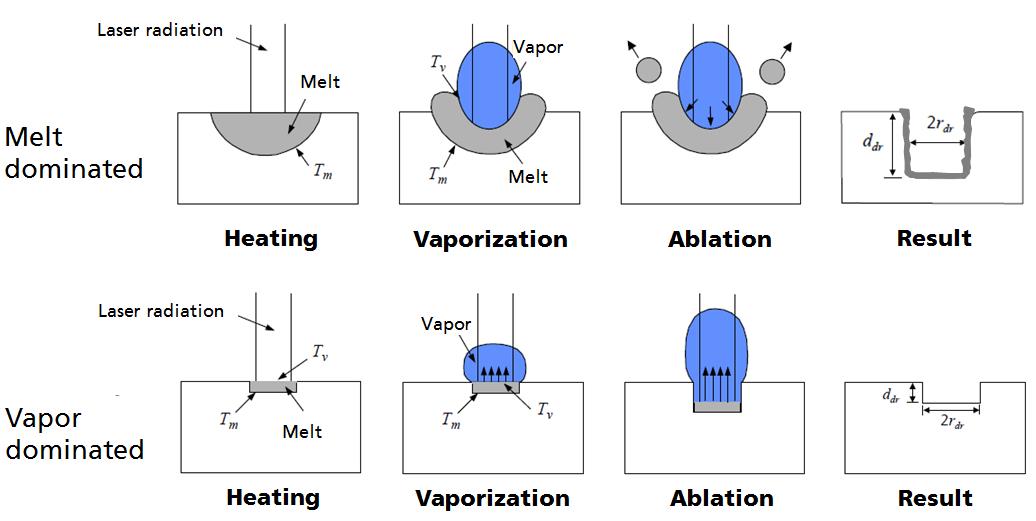
The process related microstructure changes and defects shall be reduced by using ultrashort pulsed laser radiation. Pulse durations < 10 ps are shorter than the electron phonon interaction time, so that a “cold ablation” is possible as the material is directly vaporized. Thus, the appearance of recast layers and the initiation of cracks might be avoided. The comparison of the vaporization-dominated ablation and melt-dominated ablation is shown in Figure 1.
An Amphos ultrashort pulsed laser source is used with a wavelength of 1030 nm, an average power of up to 400 W, a repetition rate of up to 56.8 MHz and a pulse duration between 0.7 and 7.65 ps. Pulse picking is applied for repetition rates smaller than 1.43 MHz by using an electro-optic modulator (EOM). Depending on the number of picked pulses the average laser power is reduced e.g., approx. 50 percent of power if every second pulse is picked (715 MHz). A conventional galvo scanner system is used for beam deflection.
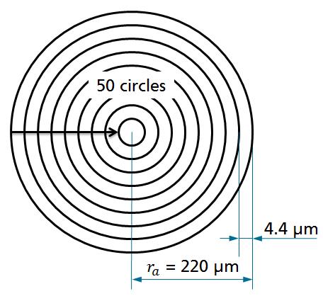
The drilling process is developed by initial experiments to drill holes with a diameter of 500 µm into 3 mm thick stainless steel 1.4301. The following aspects are investigated: The influence of type and pressure of process gas, the focal position in z-direction, the average power and the repetition rate of the laser radiation depending on the hole entry and exit diameter as well as the thickness of possibly existing recast layers. The laser radiation is deflected within a circular geometry consisting of 50 circles, see Figure 2. The diameter of the outer circle is 440 µm and the distance between any two circles 4.4 µm.
The variation of process gas is performed by using a repetition rate of 237 kHz and an average laser power of 75 W. The focal position is on the surface of the workpiece and the process gas pressure is 5 bar. The 50 circles are repeated 300 times which leads to a drilling time of 146 s per hole. As shown in Figure 3, the holes drilled by using argon and nitrogen as process gas are not cylindrical. This is caused by the inert effect of both gases. Due to less available energy, the conicity of the holes is bigger. Furthermore, the hole walls are reflective. This leads to reflections of the laser radiation at the hole wall so that break outs in the lower part of the holes occur. The hole drilled by using oxygen has an oxidation layer of approx. 50 µm in the lower part. Only the hole which was drilled by using compressed air as process gas has no recast layer. Thus, compressed air is used for all further experiments.
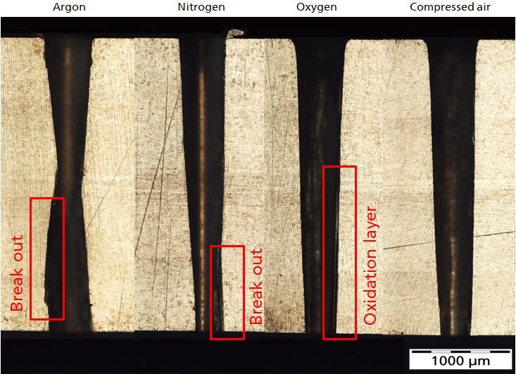
Figure 4 shows the influence of the focal position in z-direction onto the hole entry and exit diameter as well as the recast layer thickness. The hole entry diameter is not affected by different focal positions. The largest hole exit diameters combined with the smallest tolerance is achieved by setting the focal position to the middle of the workpiece (z = 1.5 mm). A continuous movement of the focal position in z-direction during the drilling process leads to smaller exit diameters.

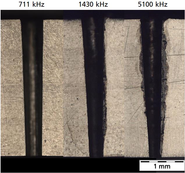
Figure 5 shows the variation of the repetition rate at an average power of 170 W. A large heat-affected zone arises at a repetition rate of 5100 kHz. The high repetition rate and the small movement speed of the laser radiation leads to a high pulse overlap of 99.94 percent. Plasma arises due to the high pulse overlap. The material at the hole wall is heated by the plasma and by following laser pulses. The effect can be decreased by using a repetition rate of 1430 kHz. At a repetition rate of 711 kHz there is almost no visible recast layer or heat-affected zone. Both, hole entry and hole exit are sharp-edged.
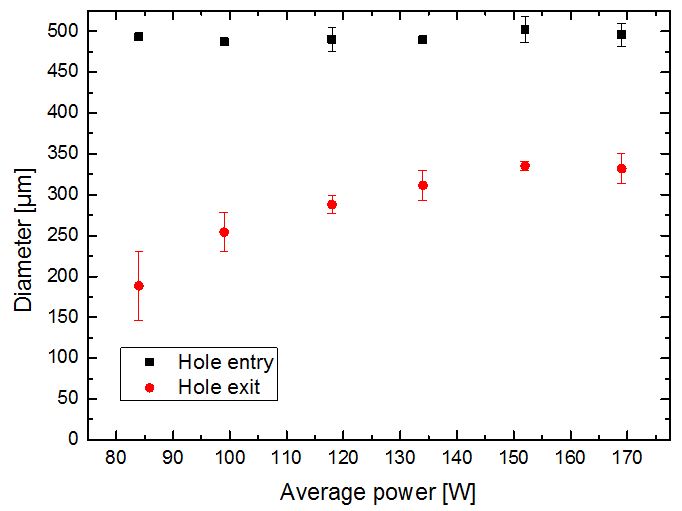
The average power is varied at a repetition rate of 711 kHz. As shown in Figure 6, the hole entry diameter is constant at approx. 500 µm. The hole exit diameter becomes larger at higher average power. The average power is limited in the pulse picking mode, which is necessary to realize repetition rates smaller 1400 kHz. Thus, the conicity of the holes cannot be avoided by varying the laser parameters.
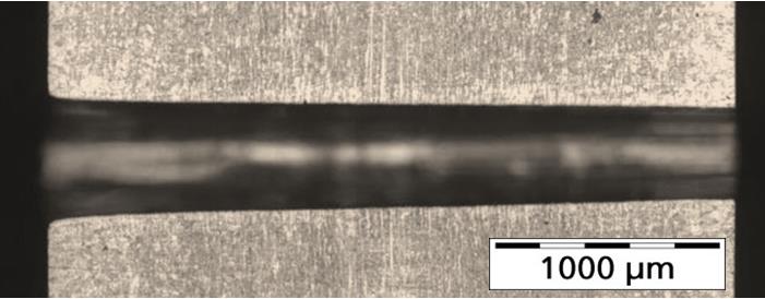
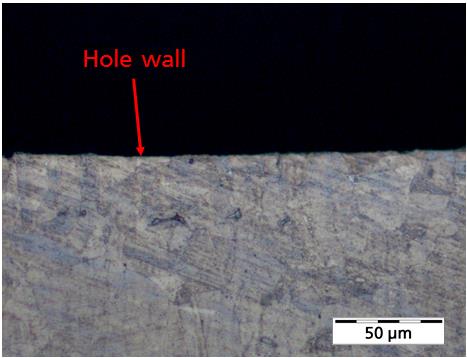
Finally, holes are drilled by using a repetition rate of 237 kHz, compressed air as process gas and a laser average power of 170 W. As shown in Figure 7 and the close-up view in Figure 8, there is no visible recast layer at the hole wall. The drilling time is 160 seconds per hole.
These are the first macro holes in 3 mm thick material drilled by using ultrashort pulsed laser radiation. Further experiments could be performed by using a helical drilling optics. Thus, the existing taper of the hole can be reduced or avoided. To decrease the drilling time, high pulse energy e.g., > 1 mJ in accordance with low repetition rates < 1 MHz should be used. As soon as the two deficits, the conicity and the low productivity, are eliminated, the drilling process could be transferred in a first step to multilayer systems consisting of base material, bond coat and thermal barrier coating. Subsequently, the process could be transferred to industry for drilling turbo machinery components such as turbine blades or combustion chambers.
Mr. Hermann Uchtmann is a research engineer at RWTH Aachen University.