


By Yujie Xu, WenWu Zhang, Zhenying Du and Liang Ruan
Laser shock peening (LSP) is a surface strengthening technology. Compared with traditional surface treatment technologies (i.e., shot peening), it has many advantages such as non-contact, no heat-affected zone, good controllability and significant strengthening effect.
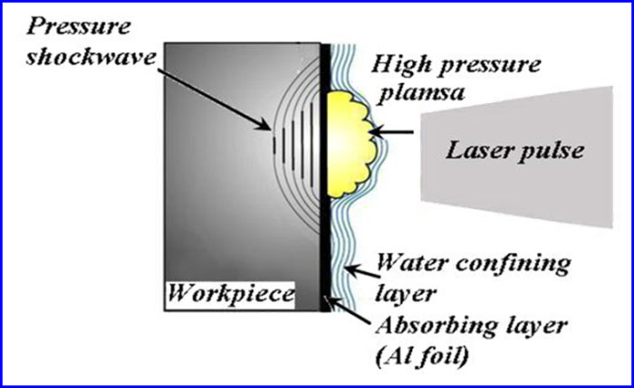
The mechanism of LSP is shown in Figure 1. In this process, a short-pulse (tens of nanoseconds) and high power (in the magnitude of 109 W) laser spot passes through the transparent confinement layer and acts on the surface of the coated absorption layer. After absorbing the laser energy, the absorption layer evaporates rapidly, and the dense plasma under high temperature and high pressure is formed. The plasma explodes as it continues to absorb the laser energy, and then a shock wave generates. The shock pressure can reach several gigapascal, far beyond the yield strength of the workpiece. The shock wave impacts the surface of the workpiece and spreads to the interior, which leads to plastic deformation in the surface layer of the workpiece. As a result of this process, the density of dislocation increases, the crystalline grain is refined, and a considerable residual compressive stress presents in the surface layer of the workpiece.
The LSP technology has made considerable progress in the recent several decades. But in the current practice, the efficiency of LSP process remained to be improved. In addition, there are two major deficiencies that need to be overcome. First, the utilization efficiency of laser energy is low in the LSP process. For the current LSP method, the plasma shock wave formed by the laser pulse half acts on the surface of workpiece, and the energy loss is about 50 percent. In order to achieve the expectant effect of surface enhancement, a high-energy pulse laser device is generally used in actual production, which is expensive and has low beam quality. Secondly, the adaptability and stability of confinement layer in the current LSP process is poor. The transparent confinement layer is commonly made of optical glass, water (the thickness of water layer is about 1 ~ 3 mm) or flexible films. Optical glass can constrain the shock wave effectively, but it is not suited to the complex surface due to its poor processing adaptability. In addition, the glass is prone to be broken under the shock, and cannot be reused. The restraint stiffness of flexible film is not high enough, and manufacturing the film is complicated. Water is widely used as the confinement layer because it is cheap, recyclable and applicable to complex surfaces, but the thickness of the water layer is difficult to control in practice and it is not rigid enough to confine the shock wave well.
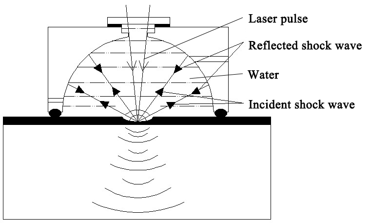
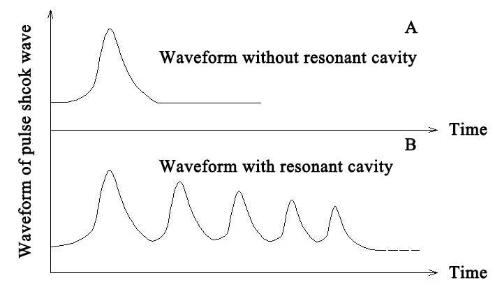
In response to these deficiencies, a patented new LSP method with a cavity used to confine the water layer is presented here, and its working principle is shown in Figure 2. The laser focus on the absorbing layer after passing through the transparent water in the cavity, and then a plasma shock wave is formed. The shock wave transforms to a composite shock wave when reflecting back and forth in the cavity (shown as Figure 3), which repeatedly acts on the surface of the workpiece. It is realized that multiple shock pulses are obtained with one laser pulse, and the energy efficiency is significantly improved. Furthermore, since the fluid is confined in the cavity with fixed shape, the issue in the present process such as poor adaptability, lack of rigidity and thickness uncontrollability can be resolved effectively.
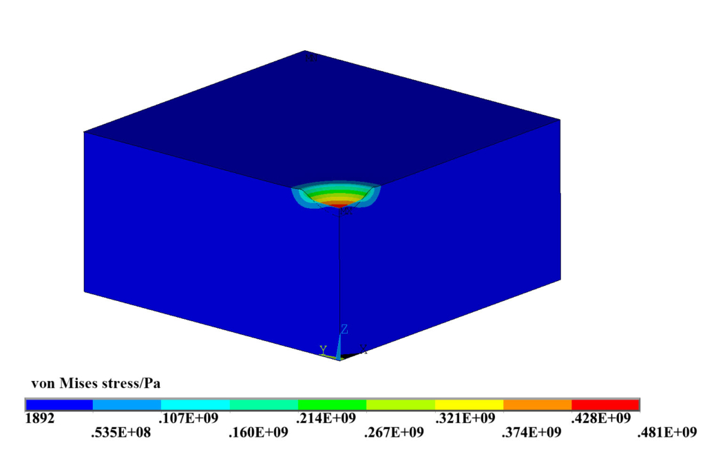
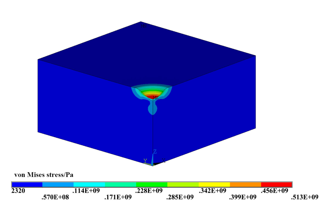
The related properties of the composite shock wave, formed in the cavity, may have significant influences on the surface hardening effect. A preliminary simulation was carried out to study two important parameters of the composite shock wave, the time interval between adjacent waves t (the time from the end of the former shock to the start of the latter shock) and the wave attenuation factor h (the ratio of the peak pressure of the latter shock to that of the former one). In the simulation, the laser spot used is circular with the radius of 2 mm. The peak pressure of the first shock wave was set to be 3 GPa. Every single shock lasts 160 ns, and the composite shock wave was supposed to be comprised of five conventional shock waves. A typical distribution of residual Von Mises stress on the workpiece treated with the traditional LSP method is shown in Figure 4. While, if the new method proposed here is adopted, the residual Von Mises stress distributed on the same workpiece increases, as shown in Figure 5.
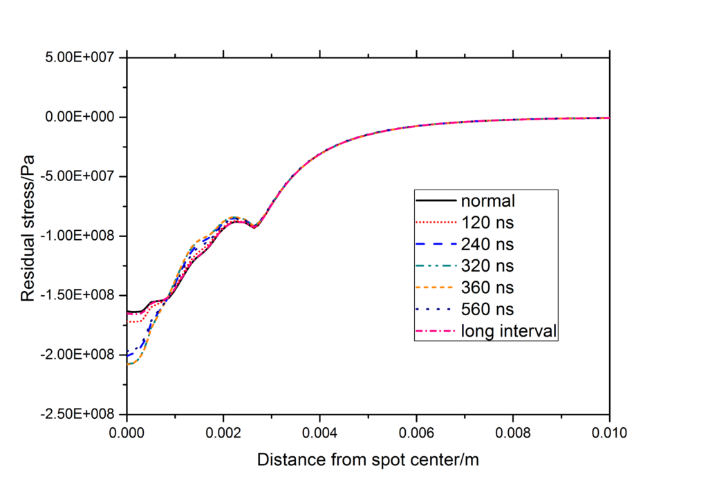
When the wave attenuation factor h=0.5 was fixed, the computations with respect to different t were executed. The calculated radial residual stress distributing on the surface of the workpiece is shown in Figure 6, in which “normal” represents the single shock in the traditional LSP processing and “long interval” represents that there is a very large interval between the two adjacent shock waves. As the value of t increases, the residual compressive stress on the surface increases first and then decreases. When t is set to be around 360 ns, the residual compressive stress reach maximum.
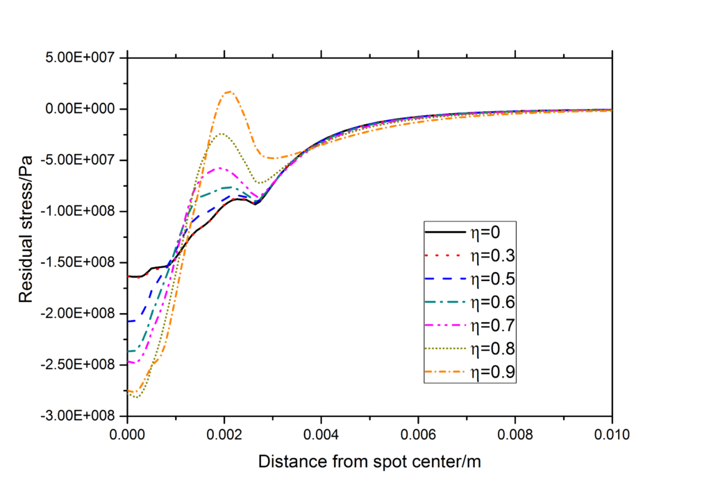
In the case that the time interval t is fixed to be 320 ns, the calculated radial residual stresses distributing on the surface with respect to different h are shown in Figure 7. It can be seen from Figure 6 that in general the residual compressive stress on the surface increases with the rising of the attenuation factor h, but the stress nearby the edge of spot varies oppositely due to the aggregation of the stress wave. When h is 0.9, there are small residual tensile stresses appearing near the edge of the spot. When h is too small, the composite shock wave no longer plays a significant role. These results indicate that an appropriate value of h should be set for the effective composite shock wave.
The simulations show that the main parameters of the composite shock wave, formed in the cavity, have an important influence on the strengthening effect. In order to provide guidance for the design of the cavity, further theoretical research needs to be carried out. The experimental work is also under way, and the new progress will be reported soon.
The authors are with Ningbo Institute of Materials Technology & Engineering (NIMTE).