


By Michael Scaggs
A lasers spot size and therefore resulting M2 or beam parameter product can be a very difficult and confusing parameter to quantify. The techniques to measure vary and often add to the difficulty and confusion. At present there is only one standard that defines the approach to measure a laser’s M2 value and is the International Standards Organization (ISO) 11146-1 (2005) publication1, “Lasers and laser-related equipment – Test methods for laser beam widths, divergence angles and beam propagation ratios.” This presentation will go over the basics of this document and how to apply it with the various M2 measurement techniques on the market. There is more than one definition on beam waist size and these definitions will be covered along with how to measure M2 using a variety of the available market techniques. Basic Gaussian beam equations (beam waist, Rayleigh length, and divergence) will be covered along with basic optical aberrations and attenuation techniques and precautions regarding polarization and thermal lensing. The goal of this presentation is to provide the participate with a basic understanding of what M2 and beam parameter product are and how they are used in the field but more importantly how one can use them in one’s own application.
What is M2?
M2 is called beam quality factor or beam propagation factor and is a common measure of the beam quality of a laser beam2. According to ISO 11146-1 (2005), it is defined as the beam parameter product divided by λ/π. It provides a quantitative means to establish how well a given laser beam will focus or diverge and is always relative to a diffraction limited condition of the same beam size and wavelength.
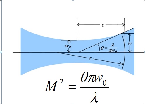
It can as well be viewed as a factor that shows how much the measured beam deviates from a perfect Gaussian beam. A perfect Gaussian beam would be a single mode, TEM 00 laser beam. A good, low noise, frequency stabilized HeNe laser is a good example of one that is very, very close to a perfect M2 of 1. Mathematically, it is defined as follows:
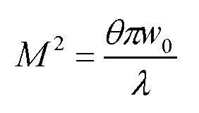
Where Θ is the beam divergence, w0 is the measured beam waist and λ is the wavelength of light.
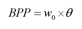
Beam parameter product (BPP) is as well related to M2 and is simply:
When M2 =1, the M2 equation can be modified to:
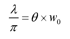
We can therefore easily see the relationship between M2 and BPP. As an example the diffraction limited BPP for a 1064nm laser would be 3.387e-7.
How to Use M2 and BPP?
M2 provides the “times diffraction limit” that a laser spot can be focused and is a quantitative value for how theoretically perfect the laser is. BPP is most useful for fiber lasers and how the beam expands from the fiber and how they will focus.
From the equations given about we can easily calculate spot size and another important parameter: Rayleigh length Zr:
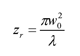
It is important to note that the Raleigh length decreases with the M2 factor. Let’s suppose a given system focuses to a 100 µm spot but has an M2 of 2, the Rayleigh range for the diffraction limited case would be +7.38 mm but would drop to +3.69 mm for the M2=2 case.
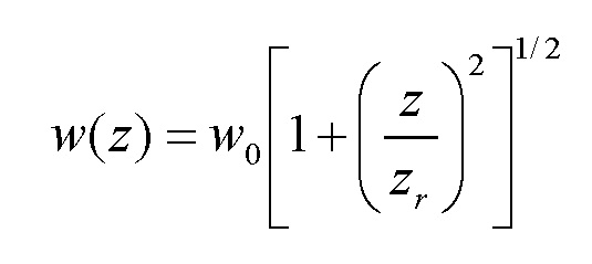
Knowing the beam waist w0 and Rayleigh range Zr, one can determine the size of the beam at any location along the optical axis using the following equation:
Measurement Methods
The ISO 11146-1 outlines the method for determining a laser’s M2.3 The existing methods available on the market today include:
- Rotating Slits/Apertures
- Spinning Needle (High Power)
- Moving Focus Lens/Sensor Along Optical Axis
- Rayleigh Scatter
- Passive optical delay
The first 3 methods involve components in motion: something spinning or translating and the measurements are time average and not real time. The last two methods involve no moving parts but the Rayleigh scattering approach is not compliant with the ISO 11146-1 as it is only analyzing the outer shell, if you will, of the beam caustic. The passive optical delay provides the minimum of 10 spatial time slices (5 within the first Rayleigh range and 5 outside the second Rayleigh range) without any components in motion and therefore provides the M2 value at the frame rate and computational speed of the computer and vision system being used.
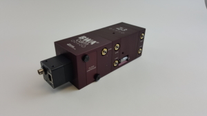
Figure 1 shows a GigE based CMOS sensor passive optical delay based M2 measurement camera. The GigE based sensor provides both the data and power to the camera and permits cable lengths as long as 100 meters which is more than a factor of 10 with USB based sensors. Moreover, the connector is very industrially robust and even for harsh environments.
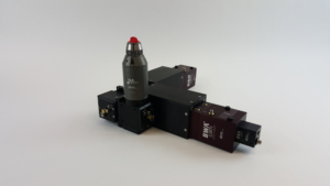
Figure 2 shows a complete measurement system for a high power fiber laser. One simply inserts a QBH based fiber in the attached collimator assembly and then the beam is directed to two attenuation wedges: one set for “P” polarization and the second for “S” and then the beam is split to two beam waist analyzer cameras (BWA-CAM). One BWA-CAM measures the 5 spots within the first Rayleigh range and the second camera measures the 5 spots beyond the second Rayleigh Range.
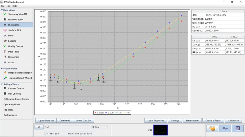
Figure 3 shows a measurement from the device shown in Figure 1. With this type of system, one can obtain the M2, astigmatism, divergence, beam waist location and many other ISO parameters within the frame rate and speed of the computer being used which is typically in the 6 to 7 frames per second.
M2 Precautions
M2 is subject to a host of experimental difficulties and is a challenging measurement to take in a traceable fashion. M2 measurements are best restricted to single Gaussian beams of good quality. “A good rule of thumb is that if a measurement of M2 returns a value great than 3, it was probably not an appropriate measurement to begin with”.
“Commercial devices that claim to measure an ISO standard M2 but do not use a digital camera are very likely using one of the alternative methods which, by the ISO standard’s own admission, are incorrect except with high-quality Gaussian beams. M2 results from these devices should also be avoided in published results.”4
ISO 11146-1 is only a method of measurement and there is no M2 standard available! You can go to NIST or other standards organizations and get your meter stick calibrated against a standard but there is no laser to which you can test your measurement system against! One therefore has to rely on the M2 measurement manufacturer to adhere stringently to the ISO 11146-1.
M2 measurement has been challenging due to:
- Attenuation issues
- Polarization
- Alignment
- Back ground noise
- Time averaging
Lack of a standard and above issues, leaves much uncertainty in any measurement.
Why Should You Care?
M2 and BPP provides a means to compare one laser against another. They are further a way to qualify and quantify a laser for a particular process. Knowing how your laser was measured is important to understand what you are getting from the vendor. A word of caution, vendors often provide 1/e2 values and not second moment! This generally provides a 10 percent to 20 percent smaller number! As a consequence, what are you really getting?
References
- ISO 11146-1:2005(E), “Lasers and laser-related equipment – Test methods for laser beam widths, divergence angles and beam propagation ratios – Part 1: Stigmatic and simple astigmatic beams”
- Paschotta, R., “M2 Factor”, Encyclopedia of Laser Physics and Technology, Wiley-VCH (2008)
- Johnston, T.F. and M. W. Sasnett, “Characterization of Laser Beams: The M2 Model, in Handbook of Optical and Laser Scanning, G. F. Marshall and G. E. Stutz, Eds., Marcel Dekker Inc., New York (2004, p. 33)
- Sean Ross, “Laser beam quality metrics,” USA: SPIE Press, 2013, pp. 80–81.Ross, Laser Beam Metrics, SPIE
Michael Scaggs is a Senior Optical Design Engineer at Haas Laser Technologies, Inc.