


UV Nanosecond Lasers Enable Finer Detail
By Jan-Willem Pieterse
CO2 lasers have long been the laser of choice for processing applications due to their power/cost ratio. CO2 lasers in sapphire create a classic melt pool, which can be blown out to achieve a full cut. However, the cut is often too crude for semiconductor applications.
Pulsed UV lasers enable machining with much finer detail, and their lack of excess heat adds another benefit — Each pulse removes a small amount of material but the high repetition rate turns it into a fast process.
Nanosecond Nd:YAG lasers can micromachine sapphire substrates of any shape and a wide variety of thicknesses. A combination of 3D cutting and a galvanometer-scanner system delivers high accuracy and edge smoothness.
Sapphire Benefits, Challenges
A recent increase in sapphire production and an associated drop in price enable new applications such as replacing chemically hardened glass or using sapphire carriers for high-powered LEDs. Yet, sapphire hardness challenges mechanical machining tools. Lasers provide non-contact machining with no tool wear and very high precision.
Sapphire is highly transparent to wavelengths between 170 nm and 5.3 μm. This lack of absorption complicates laser absorption in the material—there is little absorption at 355 nm. However, with pulsed lasers, it is sufficient to penetrate into the material and release the high intensity in a small volume. With nanosecond laser pulses, a mixture of thermal and photochemical breaking of bonds can remove small fractions of sapphire.
As a crystal, sapphire is sensitive to light polarization and scan direction. Cutting a circle with linear polarization is faster when the polarization axis coincides with the scan direction. Circular polarization was applied in the following experiments.
The Experiments
The following experiments used 30-100 ns Q-switched pulses at 355 nm and combined photo-thermal and non-linear effects to create interesting cutting results. UV interacts with twice the absorption of IR at 1064 nm, and UV also focuses to a smaller spot size, enabling the machining of finer features. High photon energy can break chemical bonds directly without dissipating into heat. On the other hand, reducing the energy close to the threshold allows for a controlled, small removal rate. Typical reported values of threshold fluence are between 100 and 300 J/cm2.
The focus of these experiments was the use of a full cut, although the results can be applied to surface scribing. Three methods were evaluated to find the best technique for a full cut of sapphire:
- Single shot in one dimension
- Line shapes in two dimensions
- Removing one surface layer and combining surface layers three-dimensionally into a full cut.
The lasers used in this evaluation were the Lumentum Q-Series Q301 and Q304. The power for both lasers delivered at the work surface was 11 W. The Q301 has a pulse width of 30 ns at 10 kHz and the Q304 a pulse width of 100 ns at 40 kHz. The divergence of 2 mRad was captured with a collimating lens to a beam diameter of 1.2 mm. Various focal diameters were obtained through a variable beam expander. The delivering focusing lens on a Hurryscan-10 galvanometer-scanner is 100 mm.
One Dimension
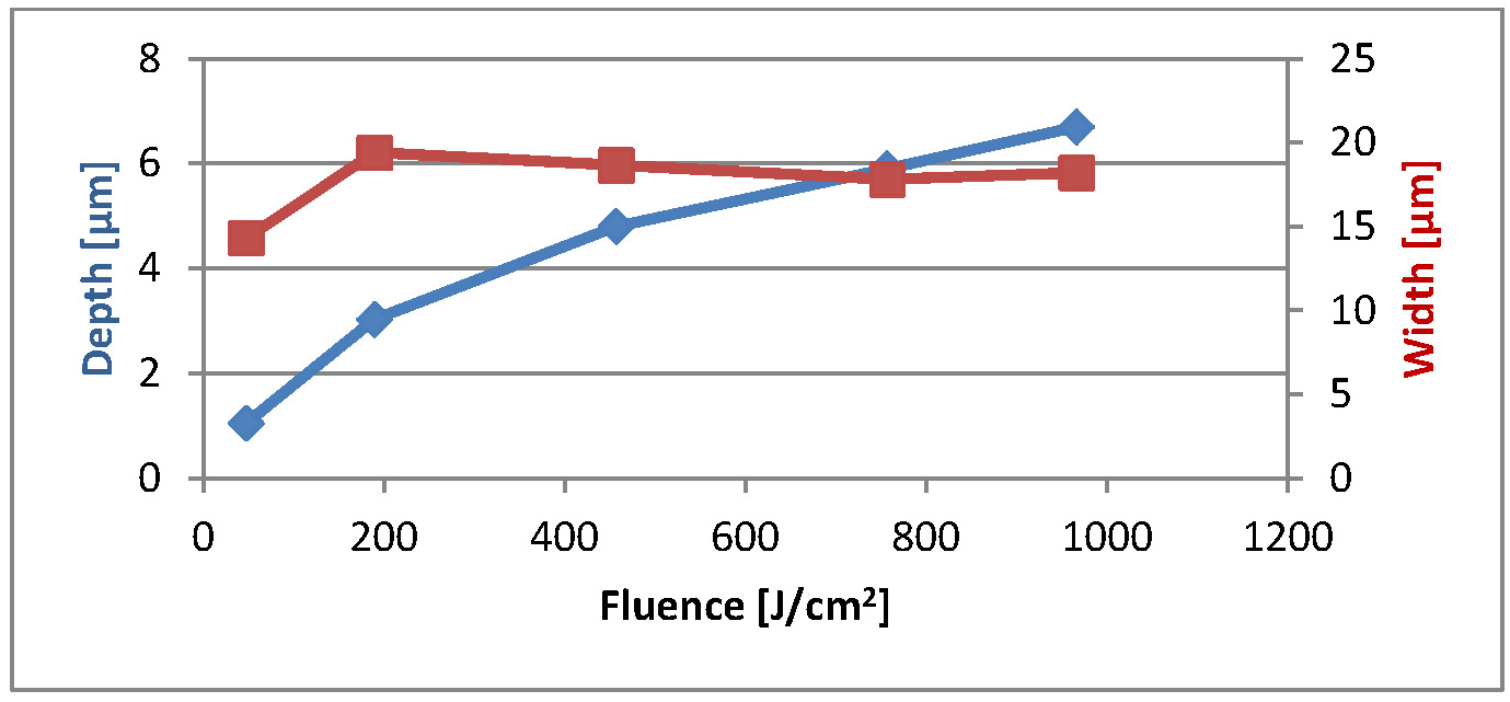
Single-shot removal involves the fewest number of processing parameters. Only the energy per pulse, the pulse width and the beam diameter (resulting in a fluence-value) are essential. It also has a pure material interaction in the absence of the plasma plume and debris. At 10 kHz, the intensity is too high for a single shot—the surface tends to crack. For the Q304, single-shot depth was deepest at the maximum available energy of 275 µJ at 40 kHz. The reported fluence is the average energy per area.
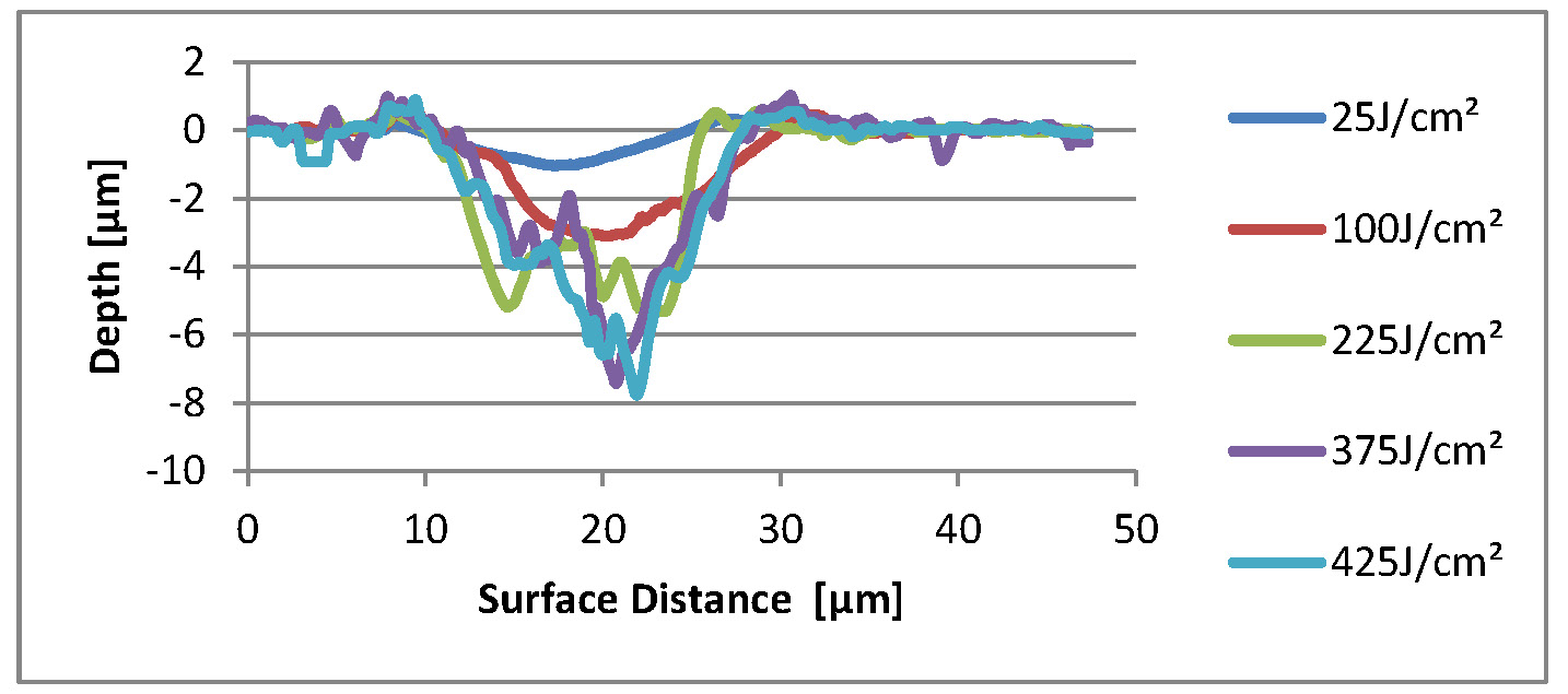
A pulse energy of 240 µJ and a 11 µm focal spot appear to be good starting values. The fluence (pulse energy and focus diameter) may need to be further optimized once a decent full cut has been established.
Two Dimensions
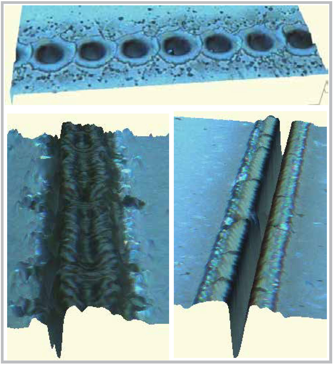
To create line-shaped geometries, laser output is scanned through a galvanometer-scanner system. Adjusting the pulse repetition rate versus the scan speed creates a pulse overlap leading to a solid line. Care must be taken when adjusting the overlap as the plasma plume and displaced material interferes with the next pulse. A quarter-waveplate converts the linear polarization into a circular polarization, resulting in equally efficient X and Y scanning.
Three Dimensions
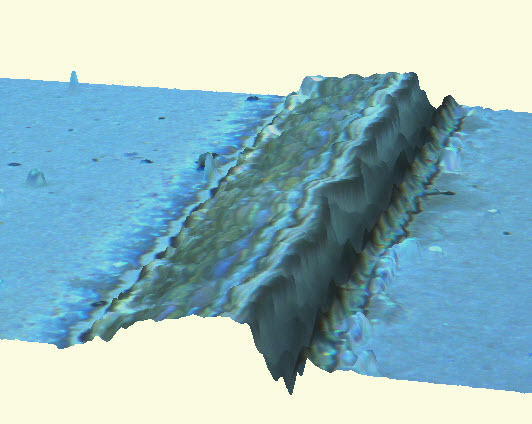
After multiple scans on a single line, the narrow opening slows down the debris escape path. A wider channel is needed to cut deeper. A common technique is to scribe multiple lines with a defined offset. The material is pushed over the previous scribe with the last scribe leaving a shallow trench. Large line pitches and slow scanning speeds result in a rougher surface. An aluminum plate under a polished sapphire sample always shows the first line marked into it. Subsequent lines (with a line-pitch less than 1 beam diameter) in a layer are not visible due to the scattering nature of the entry surface. A good parameter set is 1000 mm/s with 1 µm step size. The 1 µm pitch frees up requirements for the spot size and, with that, the overlap.
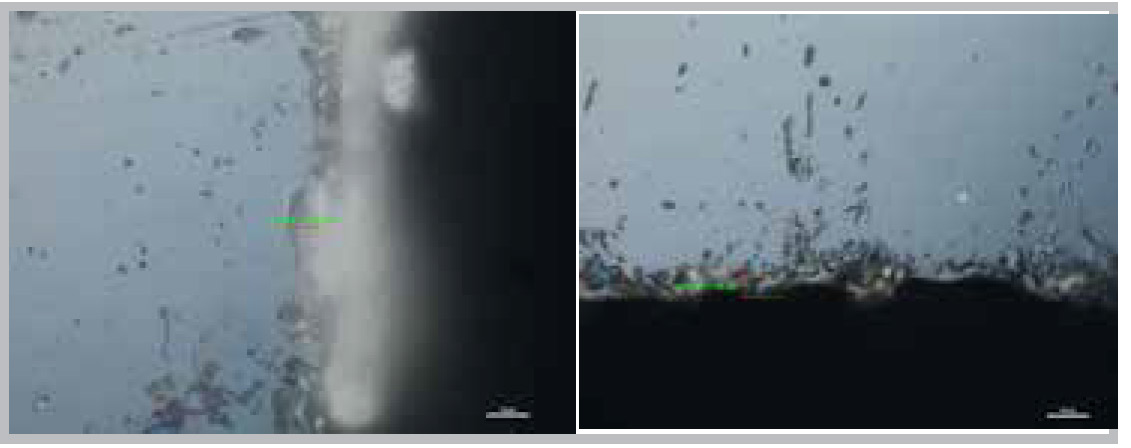
Full Cut Result
The final goal of this study was to find the fastest way to get a full cut of a 5 mm disc. With a pulse repetition rate of 40 kHz at 1000 mm/s, 10 W and a line pitch of 1 µm, this results in an effective cutting speed of 0.5 mm/s for a 300 µm thick sapphire substrate. The cut duration proved to scale with the thickness squared between 200 and 1000 µm thick sapphire. The cut duration proved to scale with the power. The record speed was 2.3 times faster with a 32 W source. Measured edge chipping was less than 3 µm, and edge surface roughness was Ra= 2.0. No cracks were observed. The edge surface roughness is optimal at large angles between the surface and the beam. Debris is easily removed with a wipe or an ultrasonic bath.
Jan-Willem Pieterse is the laser applications engineer at Lumentum.