ORLANDO, FL (February 16, 2018) – The Laser Institute of America is pleased to announce that the 2018 Laser Additive Manufacturing (LAM®) conference will be held at the Schaumburg Convention Center in Schaumburg, IL, March 27–28. For the first time in its 10-year history, the conference will be co-located with the Lasers in Manufacturing Event® (LME®). LAM attendees will be granted free access to the LME exhibit, which takes place March 28–29.
The LAM conference is an excellent networking and educational opportunity for anyone interested in working in the additive manufacturing industry or discovering laser additive manufacturing solutions for their company.
Last year’s conference chairs will reprise their roles, with Milan Brandt of RMIT University continuing as the General Chair, and John Hunter of LPW Technology, Inc. and Minlin Zhong of Tsinghua University serving as Conference Co-chairs.
The first keynote speaker, a representative from America Makes, will address the benefits of public-private partnerships in the additive manufacturing industry. On the second day, keynote presenter Ehsan Toyserkani of the University of Waterloo will discuss recent developments in additive manufacturing in Canada.
The educational sessions following the keynote speeches will feature industry experts from companies including GE Additive, Flow Science, Caterpillar, the National Institute for Standards and Technology (NIST) and the Fraunhofer Institute for Laser Technology. The presentations will cover laser cladding and welding, laser metal deposition, powder bed fusion, directed energy deposition, process monitoring, quality assurance, sensor technologies, additive manufacturing standardization and strategies for growing the metal additive manufacturing industry.
At the end of the LAM sessions, attendees will be invited to attend a reception on the LME show floor and to explore all of the laser manufacturing technology solutions LME exhibitors have to offer.
LAM is made possible by sponsors Alabama Laser, TRUMPF, LPW and Laserline. Each company will have representatives available at both the LAM and LME events to answer any questions attendees may have.
For more information and to register, visit www.lia.org/lam.
About LIA
The Laser Institute of America (LIA) is the professional society for laser applications and safety serving the industrial, educational, medical, research and government communities throughout the world since 1968. www.lia.org, 13501 Ingenuity Drive, Suite 128, Orlando, FL 32826, +1.407.380.1553.
Today there exist a number of technologies for additive manufacturing of components.
The two most prominent types utilizing lasers for generating parts out of metals are either powder bed based solutions or direct energy deposition, often referred to as laser metal deposition. As a company Laserline focuses mainly on the second type. Depending on the application it allows you to produce larger part sizes with higher productivity (deposition rates and therefore higher productivity) due to the fact of not being limited by the size of the building chamber as it would be in the case of a powder bed machine. It is also much faster in many cases.
Laserline identified four main application areas for AM in which we operate and be described based on examples in this article. Those areas include, besides generating complete parts by terms of additive manufacturing, also repair welding application or hybrid machines – a combination of conventional machining and laser technology the fourth main application area would be providing functional areas on conventionally manufactured parts.
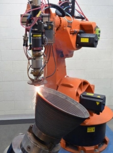
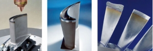
Additive manufacturing technology allows generating shapes and structures in a single production step with little material loss, post machining and tool wear (near-net-shape manufacturing). Thereby you can use material in powder or wire form. The advantage of using wire is that you will have a 100% material utilization; the compromise on the other hand might be the directional dependency when you supply the wire laterally and not coaxial. Pic. 1 shows an example of a free form application as a rocket nozzle demonstrator part made out of Inconel 625.
Pic.1 Free form powder AM of a rocket nozzle demonstrator (Source: Fraunhofer CLA)
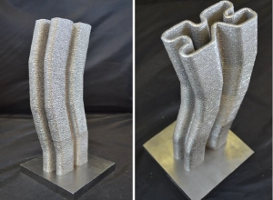
The part was done without any type of process control. Another interesting example of AM with Titanium is shown in Pic.2.
Pic. 2 Ti64 powder AM with closed loop process control (Source: Fraunhofer CLA)
Compared to the rocket nozzle, process control was used when producing the demonstrator part in pic.2. The camera based system (in this case E-MAqS) is capable of measuring the size and temperature of the melt pool. Furthermore it can give feedback to the laser source and adjust the laser power accordingly to maintain the desired size of the melt pool. This in turn ensures consistent reproducible part build ups with no defects.
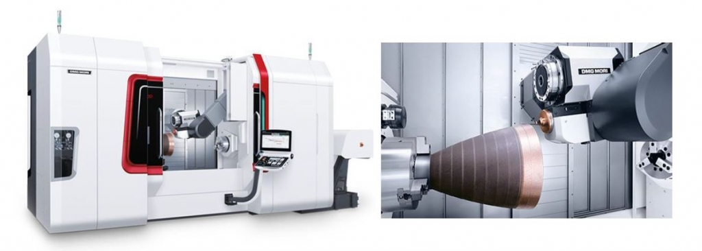
Another very interesting and promising approach is to integrate the laser source into machine tools. There are several hybrid machine tool concepts being developed; one of them is the combination of additive and subtractive tools which achieves a new level of manufacturing. One example is the merger of a laser with a 5-axis milling machine. The integrated diode laser deposits the powdered metal layer by layer, generating a solid, fully dense metal part. The following milling operations directly finish machines surfaces in areas necessary, without changing setup.
Pic.3 An example of a conventional milling machine with integrated AM technology (Source: DMG Mori-Seiki)
This flexible switch between laser and mill also allows the machining finish of areas, which would be impossible to reach on the final component. Designs with undercuts, internal geometries and overhangs without support structure are no problem. The manufacturing of completely new structures and designs are now possible. All weldable metals, which are available in powder form, can be used, for example steel, nickel and cobalt alloys as well as titanium, bronze or brass.
A third important field of AM from our perspective are repair welding applications. Probably the most prominent and widely industrially utilized are the repairs of turbine blades. Turbine blades in steam engines, especially in the first two rows, experience a lot of wear through erosion. Instead of replacing the whole part it is possible to repair the worn area by putting a couple of layers (mostly nickel / cobalt based super alloys) and machine them down to the finished surface, see Pic.4.
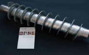
This remanufacturing procedure saves up to 90% of material and energy cost compared to manufacturing a new blade. Even though turbine blades are the most prominent example of laser repair welding a wide variety of other parts can be restored using the procedure, e.g. worm shafts, helical gears, molds, etc. to name a few. When speaking about additive manufacturing most people have the production of complete parts in mind. This doesn’t always have to be the case. Often it makes more sense from an economic standpoint to add to a conventionally (and relatively inexpensively) produced part functional areas where they are needed. Pic. 5 shows one such example.
In this case 100 lbs. of hard and wear resistant Stellite 21 powder material was deposited on a metal pipe base structure to form the extruder thread. One further example of it can be functional layers on drill bits where sensors need to be shielded from magnetic interference. By creating heat resistant layers out of non-magnetic materials it is possible to place those sensors.Through a clever combination of the usage of conventional and additive manufacturing technologies it is possible to produce advanced parts without increasing the cost.
By Irene Alfred, Boris Rottwinkel, Christian Noelke, Volker Wesling, Stefan Kaierle
Figure 1: Track parameters measured after laser cladding of single tracks while varying laser power, laser travel speed and powder feed rate
Nickel-based superalloys are used extensively in the combustor and turbine sections of aircraft engines due to their ability to withstand temperatures of up to 1100°C, thereby increasing engine efficiency. The microstructure of single-crystal turbine blades show superior creep and fatigue properties when compared to poly-crystal alloys and increase their lifespan. However, the production of such parts remains expensive and extensive as the process involves a thermal gradient to allow for directional solidification to create a single crystal microstructure. Since these parts undergo the most amount of erosion and cracking during their lifetime and no effective repair method exists, these parts must be replaced, which is an expensive process.
Our objective was to achieve a single-crystal clad on a single crystal turbine blade while facing the challenges of maintaining said structure of the substrate as well as the deposit and avoiding solidification cracks. We hypothesized that the combination of laser powder deposition and laser remelting would lead to the reorientation of the polycrystalline area and thereby extend overall single-crystal height. In order to achieve our goals, a diode laser system with a wavelength of 980 nm and a maximum power of 340 W was used. Experiments were carried out on CMSX-4 and PWA 1426 substrates as well as on turbine blades of the latter material.
Laser Cladding
The first step of the process was to carry out a parameter study in order to determine a set of laser process parameters that resulted in tracks that were free of cracks and pores and also did not diminish the crystallographic orientation of the substrate during the process of cladding. In order to do so, the primary laser cladding parameters, namely laser power, laser travel
speed and the powder feed rate, were varied and the track parameters shown in the figure below were measured.
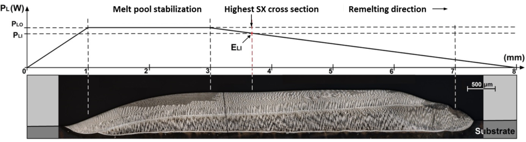
Figure 2: Laser power ramp methodology for the remelting process
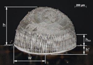
The clad height (h) was defined as the height from the surface of the substrate to the highest point, while the single-crystal height, hsx, was measured at the shortest distance between the
surface and the beginning of polycrystalline microstructure. In order to reduce the effect of process instabilities and variations of the melt pool chemical composition, hsx was measured at the
cross-sectional and longitudinal axes. The melt pool depth, h’, and the polycrystalline area, Ap, were also measured, which resulted in five tracks for further testing, the laser parameters
required to create them and the track parameters that were measured.
Laser Remelting
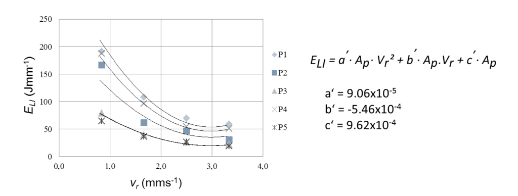
For the process of remelting, we hypothesized that ideal pairs of remelting speeds (vr) and energy inputs (ELI) that resulted in the highest monocrystalline volume would exist. These values were determined by evaluating the results of our power ramp methodology that is depicted in the figure below. The power ramp methodology involved maintaining the remelting speed at a constant value while decreasing the laser power linearly over the course of the track. The laser power was increased to 200 W prior to the start of the track in order to ensure the beginning was not abrupt, after which a short period of constant laser power was maintained to allow for melt pool stabilization prior to the linear drop in power. A descending ramp ensured that unnecessary heat would not be built up in the substrate and disrupt the thermal gradient necessary for the formation of monocrystalline structures.
The remelting process was carried out at 3.3 mm·s-1, 2.5 mm·s-1, 1.7 mm·s-1 and 0.8 mm·s-1 for each of the five tracks. Longitudinal analyses of the microstructure of the tracks were
then carried out. By determining the highest single-crystal cross section and the corresponding laser power, it was possible to determine pairs of vr and ELI values.
It was determined using the method of least squares that a second degree polynomial equation best represented the relationship between the values. In an attempt to define a single
family of equations that would allow for the determination of ELI using track parameters, the polycrystalline area (Ap) was taken into consideration in the equation and the coefficients a’,
b’ and c’ from the general second degree polynomial equation recalculated. The resultant general equation is as follows (Figure 3):
Figure 3: Relationship
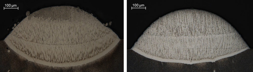
Using the above equation, a set of remelting parameters was calculated and applied to a single track of CMSX-4 and PWA 1426. As is seen in the figures below, it was possible to extend
the height of monocrystallinity past that which was created during the cladding process.
Figure 4: CMSX-4 (left) and PWA 1426 (right) substrates after cladding and remelting
Multi-layer Cladding
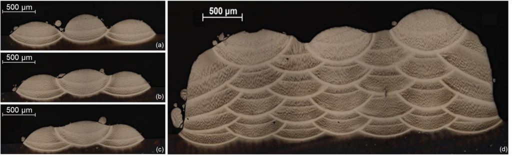
In order to create multilayered structures, the substrate orientation and heat drainage effects had to be taken into consideration. The most common strategy of creating such layers is by overlapping one track with the next. However, this could cause a misalignment of the thermal gradient and the formation of an acute angle between the new track and the substrate, which could lead to the formation of cracks and pores. In order to determine an ideal distance between the tracks, the following values were tested: 1.3 mm, 1.5 mm and 1.7 mm and the
resultant tracks depicted.
At 1.7 mm the space between the tracks is not sufficiently filled and a spacing of 1.5 mm shows a polycrystalline area at the overlap of the tracks that could be susceptible to hotcracking
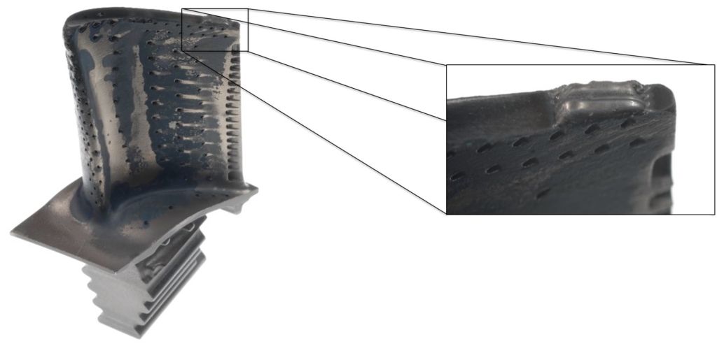
in subsequent steps of the cladding process. Tracks with the spacing of 1.3 mm showed the best results with the gap being filled and the surface creating an ideal substrate for further cladding. The multilayer clad on the right, obtained by the parameters previously deduced, showed a single-crystal structure with a height of 650 μm and a width of 3,700 μm. A complete reorientation of regions that were previously misoriented was also observed. Using the parameters deduced in the previous steps, a process was developed to perform cladding on a turbine blade tip, which
showed no macroscopic cracks as shown below.
Figure 5: Tracks with a spacing of (a) 1.7 mm, (b) 1.5 mm, (c) 1.3 mm and (d) a multilayer CMSX- 4 clad
Summary and Outlook
While our present and future work seeks to further validate this design of experiments, we were able to show that the processes of laser cladding in combination with laser remelting is a capable
tool for improving and simplifying the formation of large single crystal volumes. It was determined that ELI, the energy input per unit length necessary to remelt and reorient a track increases
exponentially with decreasing remelting speed. We were also able to define a relationship between laser parameters and track parameters during the cladding and remelting processes,
which allows us to predict and calculate said parameters.
Figure 6: Cladding on a turbine blade tip
This process shows promising results for the repair of single-crystal turbine blades and requires further evaluation with regard to the thermal properties and detailed microstructural analyses of the regenerated parts.
ORLANDO, FL, Nov. 26, 2014 — The Laser Institute of America (LIA)’s annual workshop on laser additive manufacturing moves to LIA’s hometown of Orlando on March 4-5 at the Embassy Suites – Lake Buena Vista South (Orlando, FL) for the first time in 2015. Held at Florida’s high-tech corridor, LAM promises another no-hype look at the disruptive power of additive processes.
Chaired by Dr. Ingomar Kelbassa, the seventh Laser Additive Manufacturing (LAM®) Workshop will focus heavily not only on traditional laser-based cladding applications to prevent or repair corrosion and wear, but also on the process chains vital to optimizing the additive production of parts.
By J. M. Amado, J. N. Montero, M. J. Tobar, A. Yañez
Functionally graded materials (FGM´s) are usually described as composite materials in which composition and structure varies gradually from one point to another. Traditional composites are based on homogeneous mixtures where the properties of the respective components are averaged according to their relative proportion. Therefore a compromise must be made between the desired properties of each constituent. In contrast, the need for a compromise is eliminated in FGM: the graded design ensures that the full performance of each component is obtained at some point of the composite material.
A wide range of processing methods is available today for the fabrication of graded structures with almost any material combination. Most of them rely on well established processing routes as powder metallurgy or melt processing. Direct metal deposition (laser cladding), for example, can be adopted for the production of FGM by feeding with mixed alloy powders with controlled compositions. This can be achieved by using pre-blended powders at desired mixing ratios or, even better, by using separately controlled powder hoppers. In this last case, mixing ratios can be changed online during processing. Continue reading →