Quality Assurance of Selective Laser Melting Applications

By Thomas Gruenberger

Key differentiation criteria for Additive Manufacturing (AM) technologies are freedom of design, cost advantage, customization, and time to market.

Direct metal laser sintering (DMLS) AM technology is ideal for serial production for industries like aerospace.

Setting up a process means mapping the input parameters (e.g. machine and process parameters and part geometry) to output parameters (part properties like density, tightness, surface quality). An in-situ nondestructive measurement of part properties like density is not possible, so indirect measurements have to be performed. Information from the process – process emissions, melt pool size, melt pool dynamics, and temperature distribution – can be used for this indirect measurement enabling the user to find a correlation between features of these measurements and the resulting part properties. Additionally, a shorter process development time can be achieved by avoiding destructive tests during development learning reading the extracted features (see Fig. 1).

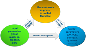
Fig. 1: Quality inspection – the challenge

As mentioned above, several pieces of information from the process can be used for the detection of irregularities, so different sensor technologies can be used. Consider a manual in-situ inspection of the process, where the user looks at the visible process emissions in the process chamber. Differences in brightness, size, color, and number of sparkles can be detected with the human eye. This can be automated using photodiode based meltpool monitoring systems like the plasmo fast process observer, a hardware developed by plasmo with up to 4 channels at sampling rates up to 300kHz.

So the system measures the brightness of the process emissions over time (blue curve in Fig. 2), using CAD data, the data can be mapped easily to an image of brightness of process emissions over the building platform (see Fig. 2 right plot), layer for layer, in pseudo color representation.

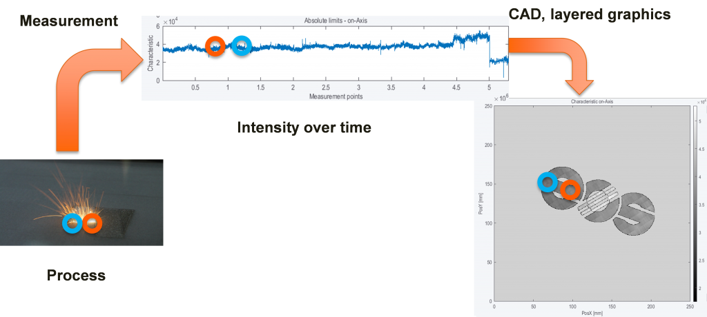
Fig. 2: Feature map of the building process

Running an OK process gives the baseline of the feature, provoking process irregularities yields in a change of the feature, enabling the user to set limits for the feature according to its quality needs. A pseudo color representation of a map of process irregularities can be calculated, giving the user an easy way to understand visualization and therefore, fast feedback about the quality of the process. As a note, black means no process irregularities and yellow means 100 percent of process irregularities in the given pixel in Fig. 3.

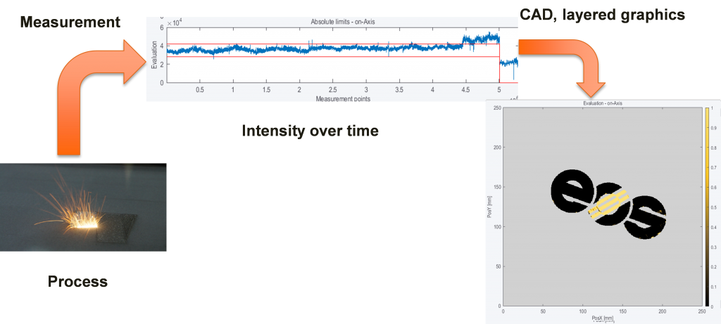
Fig. 3: Map of process irregularities

The fully automated measurement system enables a 100 percent inspection of the building process. The high sampling rate (ca. 10,000 times fa

ster compared to the human eye) enables the system not only to calculate features like signal height but the additional analysis in time, frequency and time scale domain can be performed, too. Three (3) different algorithms (features) are calculated by the system and each algorithm can be parametrized according to the quality needs for every exposure type used in the layer.

These algorithms are easy to explain. Based on physics, they correspond directly to process different phenomena.

  • Absolute limits: Influences in the size and form of the cross section of one exposure like focal position, laser power and welding speed
  • Signal dynamics: Noisy processes or less process dynamics like pollution, protective gas flow and lack of fusion
  • Short time fluctuations: Short changes in the signal caused by e.g. ejects and pollution

In cooperation with EOS, the described system was integrated with their machines. A typical layout is shown in Fig. 4.

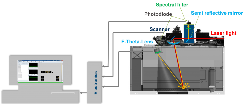
Fig. 4: System layout – EOSTATE Meltpool

As shown in Fig. 4, two total photodiodes are used an onAxis diode measuring the process emissions at the interaction zone of the laser beam and powder and an offAxis diode giving an overview of process emissions about the complete building platform.

A heuristic model is used for setting up the system; therefore, input parameters like process parameters (laser power, scanning speed, gas flow, …) and malfunctions like loss of laser power, and material quality are varied for different building jobs. The output parameters are part properties (porosity, surface roughness, …), process emissions (brightness, temporal behavior, spectral properties, …) and undesired effects like overheating, warpage and lack of fusion. Based on this data set the system can be parametrized to fulfill the quality needs of the customer.

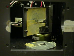
Fig. 5 shows a provoked malfunction, missing powder choosing a too low dosing factor of powder, the irregularities (here red in Fig. 5) can be easily detected.

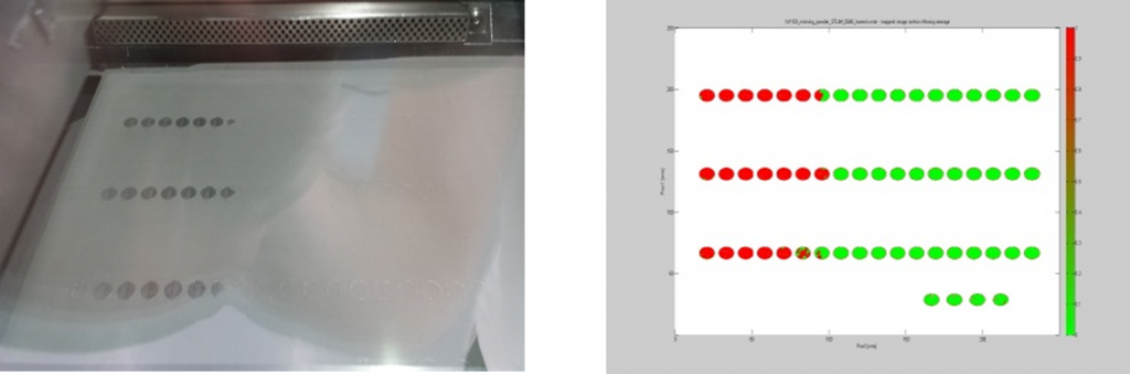
Fig. 5: Example missing powder, left image of powder bed, right calculated irregularities after exposure

Fig. 6 shows a phenomena process flipping provoked by changing the focal position, the irregularities (red in Fig. 6) can be detected successfully for the complete parts and also the embedded parts (letter F).

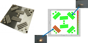
Fig. 6: Example process flipping, left image of building platform after complete build, right calculated irregularities

Successful detection of additional phenomena has been shown:

  • Overhanging parts
  • Dust/particles
  • Part overlap
  • Balling / humping
  • SLI pores (simulated porosity)
  • To be continued.

The presented diode based meltpool monitoring system enables the fully automated detection of process phenomena (see Fig. 7) which directly corresponds to part properties.

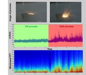
Fig. 7: Example stable and unstable process, top image of process emissions, middle measured brightness, bottom windowed FFT analysis

Easily understandable algorithms based on physics are applied and can be parametrized by the user according to its needs. A heuristic model for setting up limits was presented and examples of detectable process phenomena are given. The system is part of an integrated quality inspection portfolio at EOS including EOSTATE powderbed and EOSTATE system monitoring.

Further investigations in detectable process phenomena and self-healing effects of defects will be completed. Additional work is in progress in the field of statistical data processing, so information (see Fig. 8, e.g. trends, …) is extracted from data visualized in dashboards enabling the user to perform statistical process control (SPC) at one machine up to different machines at different locations worldwide.

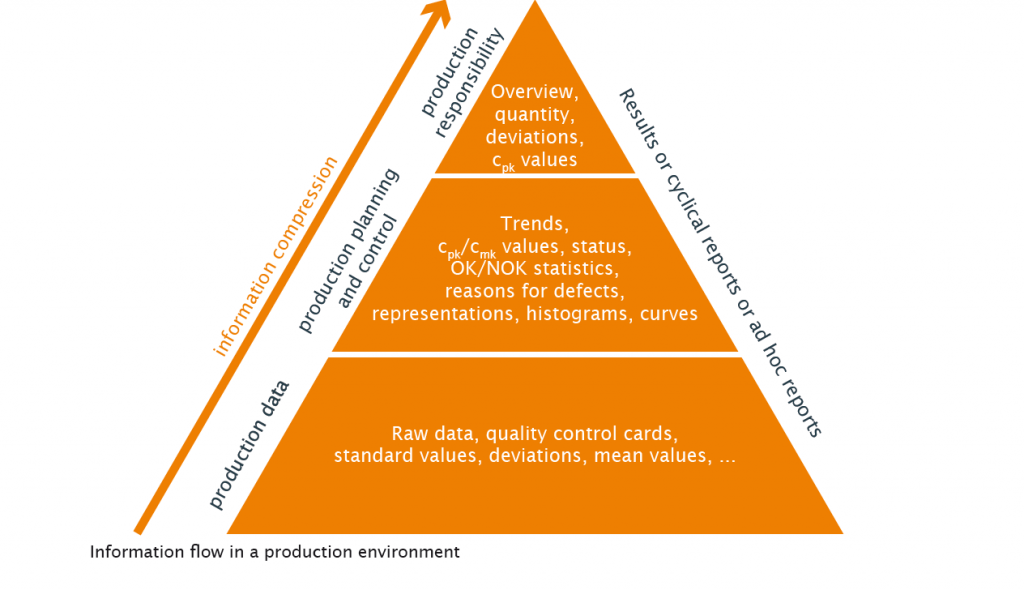
Fig. 8: Statistical process control

About plasmo 

Headquartered in Vienna, Austria, plasmo is an innovative, globally operating technology company for automated quality assurance systems in manufacturing industries. Established in 2003, plasmo leads the way in the real-time quality control of joining processes. The extensive portfolio in the field of quality assurance includes laser power measurement, the monitoring of welding processes, geometric shapes and surfaces, tailor-made solutions in the field of industrial image processing, analysis software as well as an extensive range of services.

With over 700 plasmo systems in operation worldwide, the growing list of clients includes ABB, Benteler, BorgWarner, Faurecia, INA, SMS Siemag, Hettich, JCI, Magna and Valeo to Webasto, and numerous automobile manufacturers such as Audi, BMW, Daimler, Ford, GM, PSA, Suzuki, Volvo as well as various international steel manufacturers. www.plasmo-us.com

© 2017 Dr. Thomas Grünberger, plasmo Industrietechnik GmbH, Vienna


Proposal of a New Laser Safety Guard Material & Its Protection Time Evaluation Method

KUNIHIKO WASHIO, TAKASHI KAYAHARA, YOSHIHIRO EMORI AND AKIRA FUJISAKI

Thin metallic sheets made of aluminum or steel with a thickness of 1 to 2 mm are often used as laser guard materials. However, metallic laser guards are easily penetrated by high power laser irradiation due to quick melting.

Therefore, their protection times are short. Current problems of metallic laser guards are: (1) A tendency toward generating a large through hole due to quick melting if irradiated with high-power laser; (2) Protection times are significantly influenced by surface reflectivity conditions and reflectivity changes over time.

Contrary to ordinary metals, pitch-type carbon fibers have desirable features such as non-melting, high-sublimation temperature and low-reflectivity. Therefore, we have conducted experiments to evaluate pitch-type CFRP (carbon-fiber reinforced plastics) as a new guard material for high-power lasers. These 3-mm thickness, lightweight CFRP plates incorporate industry grade pitch-type carbon fibers K13916 having tensile modulus of 760 GPa, fabricated by Mitsubishi Plastics Inc. The specific gravity is only 1.7. The CPRP plates consist of stacked multilayers with carbon fiber orientation orthogonal to each other, layer by layer. The carbon orientations of the top and bottom layers are designed to be in parallel. The fabricated CFRP plates have strong anisotropy in thermal conductivity: 60 W/(m•K) for X and Y directions vs. 1 W/(m•K) for Z direction. Therefore, the heat generated at the irradiated front surface is effectively prevented from reaching the rear side due to the very low thermal conductivity in Z direction.

Figure 1 shows the schematic diagram of experimental setup. A CW fiber laser capable of emitting up to about 10 kW at a wavelength of about 1,070 nm was used. The laser beam was irradiated at test samples with a focusing lens having focal length of 300 mm. The length L from the focal point to the test samples was adjusted so that the irradiated beam diameter becomes either 60 mm or 30 mm. Two silicon photodiodes PD10 and PD11, equipped with 50-nm bandwidth bandpass filters having different center wavelengths (1,075 nm and 1,000 nm, respectively), were used in the front side to differentiate scattered laser radiation and thermal radiation.

Figure 2 shows the layout of eight photodiodes located on the back plate inside the shielding box. Seven photodiodes from PD2 to PD8 are with bandpass filters having a 1,075 nm center wavelength. One photodiode PD12 is with a bandpass filter having 1,000 nm center-wavelength. All the photodiodes were used in photovoltaic mode without applying any bias voltage. The output waveforms from the photodiodes were simultaneously recorded with a 10-channel data logger. The input resistance of the data logger was set to be 2.4 kΩ.

Three different types of materials were used for test samples. They are: 3-mm-thickness CFRP, 1.6-mm-thickness zinc-coated steel and 1.5-mm-thickness aluminum. The top surfaces of aluminum test samples were gray coated to suppress strong reflection. Two types of sample-holding arrangements were used for test samples having two different sizes. One arrangement is for 300-mm-square, larger size samples and is designed to thermally insulate them from the shielding box to ensure natural air cooling. The other arrangement is for 150-mm-square, smaller-size samples and is designed to test small samples economically by utilizing partial and indirect peripheral cooling by attaching the sample to a rear-side panel having four watercooled heat sinks. Figure 3 shows pictures taken during and after laser irradiation for a 300-mm square, pitch-type CFRP test sample.

Table 1 shows the comparison of test results for partially and indirectly cooled, 150-mm-square test samples irradiated with 60-mm-diameter laser beam at 3 kW. Average values of experimentally measured penetration times for ten samples of 1.6-mm-thickness zinc-coated steel and 1.5-mm-thickness gray-coated aluminum were 55.89 s and 3.96 s, respectively. The relevant standard deviations were 3.13 s and 0.14 s, respectively. Penetrated large holes are clearly visible for metallic test samples. On the other hand, for the case of 3-mm-thickness pitch-type CFRP, we could not observe any penetration for all the tested ten samples, even after more than three minutes of irradiation, although slight texture and color change could be seen on the rear surfaces.

When pitch-type CFRP test samples were irradiated with laser beams having much higher irradiation densities, we could observe rising, but from complex signal waveforms from the photodiodes located inside the shielding box. To interpret photodiode signal waveforms, a small mirror was placed in the rear side to monitor the phenomena occurring on the rear surface. By comparing the video data and photodiode signal waveforms, we have found that rear-side ignition starts much earlier than the penetration, or burn-through. Therefore, we have decided to use this rear side ignition time, instead of penetration time, as the experimental limiting time-base for the statistical calculation of protection time.

Figure 4 shows an example of irradiation test results for 300-mmsquare, larger size, naturally air-cooled CFRP test samples, irradiated with 30 mm-diameter laser beam at 9 kW. The rear side ignition time has been measured to be 23.5 seconds for this sample. A tiny hole can be seen in the bottom picture for the rear surface. Figure 5 a shows histogram of rear-side ignition times observed for 300-mm-square, naturally-air-cooled ten test samples.

The average value of rear-side ignition time has been measures to be 24.89 s with standard deviation of 3.61 s. From these data, the protection time of 3-mm-thickness pitchtype CFRP plates for irradiation of 30 mm-diameter laser beam at 9 kW (power density of 1.27 kW/cm2) has been calculated to be 9.8 s, which is very close to satisfy T3 class condition of minimum inspection interval of 10 s according to IEC 60825-4 Ed. 2.2: 2011, Safety of laser products – Part 4: Laser guards.

In conclusion, it has been demonstrated that lightweight pitchtype CFRP plates (with density of about 1/4 of steel) can provide remarkably long protection time against multi-kW high power fiber laser irradiation when used as a passive laser guard. Pitchtype CFRP would be also useful as a key component material for construction of active laser guards. It must be pointed out here, however, that proper precautions against the flames and fumes generated at the irradiated front surfaces of pitch-type CFRP plates become necessary.

The authors greatly acknowledge funding of METI standardization project “International Standardization for Highly Laser-Resistant Laser Guards.” The authors also thank the committee member of OITDA on high strength laser guards for helpful and valuable discussions and encouragement. Kunihiko Washio is president of Paradigm Laser Research Ltd. Takashi Kayahara, Yoshihiro Emori, and Akira Fujisaki are engineers at Furukawa Electric CO. LTD.

Laser Safety in Entertainment Applications

By James Stewart, CLSO

High power lasers are routinely used in entertainment environments as a special lighting effect. Historically such lasers could only be used in situations where the budget, infrastructure, (namely power supply and cooling), and space permitted.

In recent years, however, these barriers have disappeared with the proliferation of low-cost solid-state laser light sources that now dominate this sector. This has created new opportunities in how the effects are being used, as well as who is able to now use them.

Business is healthy for the specialist laser effects providers that typically supply lasers for events and music performance tours, using output powers ranging from 1W through to 40W CW, with not a drop of water or three-phase in sight. Dramatic reductions in the purchase cost, physical size, and power supply requirements have influenced how the effects are used. Ten years ago, a typical music concert touring application would employ a single digit number of laser effects projectors, with output powers ranging from 3W to 10W. The same types of installation in 2017 are typically using 30 to 40 fixtures, with a range of output powers up to 30W or more. The greater number of lasers being used on single installations has increased the need for better awareness of the exposure risk, and

The greater number of lasers being used on single installations has increased the need for better awareness of the exposure risk, and requirement for a robust installation protocol. In a change to earlier practice where a dedicated laser operator and control system were used to operate the laser effects, many of the latest generation laser lighting effects are designed to operate directly from the same control systems as normal stage lighting effects. This has benefits from a creative perspective, in that that a lighting designer no longer needs to interface through a third party dedicated laser system operator. But the downside is that the lighting designer may not necessarily be familiar with the risks in using Class 4 laser products.

A lack of familiarity of exposure risk also exists for another new group of users, which with laser projectors costing only a few hundred dollars, and being widely available online through disco / stage lighting distributors, can install laser effects in small venues and for mobile discotheques. At the budget end of the market are multicolour laser effects projectors that produce moving beams and pre-programmed animated graphics and text. These devices typically output 1W – 2W, and operate automatically in sound-to-light mode.

Exposure potential from laser lighting effects can be considered when the characteristics of how the effects are produced is understood. The majority of lighting effects created at laser installations are through movement of two mirrors placed orthogonally, so as to move the beam freely about an imaginary x and y-axis. The maximum extent of beam deflection is typically between 50° – 60° optical.  In practice this leads to typical scan across-the-pupil exposure durations of a few µs to several hundred milliseconds, depending on the content material. Stationary beam creation is also possible if the control signal is held constant, or fails.

The other popular method of creating laser effects is achieved by passing a laser beam through a transmissive diffractive optical element (DOE), (also referred to as a diffraction grating), that splits and deflects the beam creating arrays of lesser-powered beams creating a geometric pattern. The DOE is normally attached to a motorized substrate, typically able to rotate from stationary through to 10rpm – 20rpm. The characteristics of the DOE determine the visual appearance of the laser effect produced. The time it takes a diffracted beam to scan across-the-pupil distance typically varies from a few milliseconds to being stationary.

The majority of exposures occur in the millisecond and microsecond domain, meaning for MPE comparison radiant exposure expressed in J·m-2 is used, however, for the purposes of risk assessment, it is more convenient to consider the exposure having been converted to a peak irradiance.

The hazard distance (NOHD) of most lasers used for lightshow applications normally exceeds the length of the working, (and viewing), space they are being used at. Table 1 shows the NOHD, along with the irradiance at five distances that may be representative for four typical laser output powers used in this sector. For each distance, a 0.25s and 1ms dose are considered, to give an indication of how many times in excess of the MPE such an exposure may be at that distance.


Laser Power 3 10 20 30 W
NOHD 387 707 1,000 1,225 m
Exposure Distance 5m Irradiance 60 199 398 597 kW·m-2
250ms dose 2,345 7,815 15,630 23,446 Excess
1ms dose 590 1,966 3,931 5,896 Excess
10m Irradiance 23 75 151 226 kW·m-2
250ms dose 888 2,960 5,919 8,879 Excess
1ms dose 223 744 1,489 2,232 Excess
30m Irradiance 4 12 23 35 kW·m-2
250ms dose 138 459 919 1,378 Excess
1ms dose 35 116 231 347 Excess
50m Irradiance 1.4 5 9 14 kW·m-2
250ms dose 54 178 356 534 Excess
1ms dose 14 45 90 134 Excess
100m Irradiance 0.4 1.2 2.4 3.6 kW·m-2
250ms dose 14 47 94 141 Excess
1ms dose 3.6 12 24 36 Excess


Table 1  A comparison of exposure potential of four laser output powers typically used in lightshow applications

The figures in Table 1 demonstrate how the irradiance present at the exposure distances is significantly higher than the 25W·m-2 and 101W·m-2 MPE limits (0.25s and 1ms respectively). Areas within several metres of the source are particularly high risk exceeding the MPE by several hundred, if not, thousand times, depending upon the laser power and duration. Such viewing conditions could occur for lasers positioned on, or directed at the stage from the vicinity during a poorly managed performance or rehearsal. It is also possible that the exposure could occur when the scanning position of the lasers are being lined up during the installation phase, where a stage may be occupied by technicians and crew unaware of the exposure risk.

With laser effects capable of producing exposures with peak irradiances of several kW·m-2 over a considerable distance from the source, controls are necessary to limit exposure to levels considered safe for viewing. In the first instance, the user and those sharing the environment lasers are being used in, need some appreciation of the risk and what precautions should be typically adopted. As with most projects, spending time at the early stages of development helps to identify and address issues that could become more significant if left unchecked. In an ideal world, the laser provider would be contacted early on in a production’s development, be provided with a full brief from the client, and full information about the rest of the production’s implementation. It is recognised that events rarely function like this, which is no fault of the laser provider, but instead the nature of the sector. This means the successful laser provider has to remain alert, and often has to anticipate factors that could affect safe laser use. Even the best planned productions can be dynamic environments with tweaks and changes happening right up to the last moment. Basic rules however help to keep a laser install on track and minimise the risk to workers and audience alike. At no point should users neglect the fact that laser lighting effects are a special effect, and should be regarded as such, needing appropriate precaution to be taken for their safe use.

Presently, two major standards organisations have working groups producing specific guidance for this sector. ANSI through Z136.10 – Safe Use of Lasers in Entertainment, Displays and Exhibitions (currently under development), and IEC through IEC/TR 60825-3 – Guidance for Laser Displays and Shows, will each address the issues that have become apparent as laser light show technology has become more accessible, and is being used in ways that would have just a few years ago been impractical. It is hoped that when the new guidance is available that it will provide end users and safety advisers alike with an authoritative reference to best practice for this application of lasers.

James Stewart works for LVR Optical, based in the UK, as laser safety practitioner with a keen interest and experience in managing entertainment applications using lasers. He is the project lead for IEC/TR 60825-3.

***

Interested in Laser Safety? To learn more about Laser Institute of America’s International Laser Safety Conference, visit the conference website


Setting Up a Laser Lab? Avoid the Pitfalls

By Jamie J. King, CLSO

The design of a laser laboratory is not only critical to its overall functionality, but more importantly to the safety of those who work in and around it.  The safe planning of a laboratory is no accident.  From conception to commissioning of the laser, safety must be involved in every step of the process.

Each situation presents unique challenges with equally differing solutions.  It is up to, and the responsibility of, the Laser Safety Officer (LSO) to ensure that each Laser Controlled Area (LCA) is fashioned in the safest way possible.  American National Standards Institute (ANSI) Z136.1-2014 states that the total laser hazard evaluation is influenced by:

  1. The laser’s capability of injuring personnel or interfering with task performance.
  2. The environment in which the laser is used.
  3. The personnel who may be exposed to the laser.

The laser part sounds like the simplest problem to solve.  This may have been true in the days before ultrashort pulse lasers, OPAs, nonlinear optics, and high-average power lasers, to name a few.  Today you may be faced with several of these aspects all at once. The LSO must be part of the design phase very early on to ensure all issues are addressed.

The environment in which the laser will be used is probably the biggest variable to deal with.  Being involved in the process early will ensure the crafting of a space that depicts excellence in terms of form, function, and safety.  Coming in late can be a disaster, requiring patchwork fixes that look sloppy and may not be safe.

You can minimize the extent of personnel potentially exposed by controlling the design of the laser space.  Reducing the potential for exposure to personnel decreases the hazard and downgrades the level of safety training required.  This will lessen the overall per annum operational expenses.

In setting up a laser lab, the pitfalls can be a plenty.  Without forethought, you won’t recognize them until the space is completely built out and you are ready to operate.  Any new design or remodel should incorporate the use of a computer-aided design (CAD).  With this, you can start to envision the potential problems that might unfold otherwise.   Working with the end user, you can discuss the intended operation and process flow.  Some of the potential issues you will uncover are:

  • Entryway controls – whether defeatable or non-defeatable Safety Interlock System (SIS) you can determine if you might have potential laser beam outside of the LCA.
  • Ergonomics – what tasks/operations will be performed frequently? Design the height of the optical table accordingly.  Can the worker perform all actions comfortably?
  • Utilities – electrical cables, water lines, fire suppression, and ventilation are best thought out and designed early on. Having these engineered in at the beginning prevents patch work fixes after, which surely will create slip/trip/fall issues.

In looking at the layout of the optical tables, you can determine how best to plan the beam path.  It is never a good idea to direct a laser beam towards the entryway.  If you operate in a seismically active area, you should either brace your tables or locate them such that egress will not be inhibited in the case of an earthquake.  As soon as an optical table is installed in the space you should electrically bond it to ground.  You never know that will be put on the table in the future.  Do not make the mistake of connecting a bonding strap to the bottom of the table unless you ensure there is electrical continuity between the top and bottom plate.

Something to keep in mind in setting up a safe laser operation is that you want to control the hazard as close to the source as possible.  Things to look at here are:

  • Beam Blocks/Barriers/Enclosures – beam blocks are placed at the end of beam lines or behind optics and are expected to take the power/energy of a full beam. Choice of materials is crucial here in that you don’t want to select something that is highly reflective or can’t handle the thermal load of the incident beam.  Remember that the go-to material of black anodized aluminum is very reflective in the near infrared.  Barriers are installed beyond beam blocks, usually around the perimeter of an optical table.  They are only meant to see a diffusely scattered beam.  Barriers can also be used to block an area, preventing line of site into an LCA.  Barrier materials can range from laser curtain material to metal panels or even walls.  When installing these types of barriers, one must ensure that physical stature of the worker is considered.  This will ensure that the height of the barrier is adequate to protect all outside of the LCA.  In more mature and static operations, one can employ an enclosure to take the laser hazard away from the worker.  For truly Class 1, the panels must be either interlocked or require a tool for removal.
  • Shutters – this is one of the most significant components of a safe operating laser. Limit the open space between source and shutter.  Is the shutter in place?  This may seem like a ridiculous question, but if your SIS does not have feedback capabilities, how do you know it is even there?  Shutters should be “fail-safe,” meaning they will close on a failure.  Shutters can and do fail internally and may need to be inspected to ensure proper operation.  Failures may be broken blades, mirrors, levers, and even drilled holes.

Failures may be broken blades, mirrors, levers, and even drilled holes.

The use of multiple wavelengths creates a nightmare when trying to find adequate laser protective eyewear.  Early involvement of the LSO in conjunction with your laser eyewear vendor can help determine what wavelengths can and cannot be blocked.  A safe worker is one who can adequately see what they are doing.

What about high intensity/high power lasers?  This presents another set of unique challenges altogether.  At levels of >1015 W/cm2, the generation of ionizing radiation is possible.  A 25kW laser beam with a peak irradiance of ~10 kW/cm2 can cut through simple drywall in a second.  With diffuse reflections being the main concern for barriers and enclosures, this may become a real issue.  Limited commercially available items rated at these high outputs may necessitate that you become your own tester of materials.  In this realm, you are better off just removing the worker from the hazard and go with remote operations.

The result of a well-planned laser laboratory not only promotes pride in the team that will use it, but it fosters safety.

The result of a well-planned laser laboratory not only promotes pride in the team that will use it, but it fosters safety.

How?  The space will be well engineered from the start with safety built-in.  There is less reliance on administrative controls, and with the LSO input from the start; the worker sees that their safety is the utmost concern.

FDA’s Proposed Change to the Regulation of Laser Pointers

By Patrick Murphy

In October 2016, the U.S. Food and Drug Administration (FDA) put forth a preliminary proposal to declare green, blue, yellow and violet laser pointers as “defective.” Only orange-red and red laser pointers would be allowed to be manufactured, imported or sold in the U.S.

This proposal was in response to the thousands of illegal and unsafe laser pointers aimed at aircraft in the U.S. According to the Federal Aviation Administration (FAA), pilots reported 7,442 laser incidents in 2016 — more than 20 every night. 91% of the incidents involved green laser light.

Laser Illuminations reported to U.S. FAA, annual total

Safety experts are most concerned about the bright light from laser pointers causing distraction, glare and temporary flash blindness. When visual interference occurs during critical phases of flight such as takeoffs, landings, low altitude maneuvers and emergencies, there is potential for an aircraft accident. Visual interference also has disrupted police and rescue missions.

Pilot groups and lawmakers have called for restrictions on pointers, especially green ones. For example, in February 2016 Sen. Chuck Schumer (D-N.Y.) met with the incoming FDA commissioner, who agreed to consider having FDA ban the sale of green pointers.

To understand FDA’s proposal, it is helpful to describe how FDA can change its regulations, and what a finding of “defective” means.

Under 21 CFR 1040.10 and 1040.11, FDA has limited regulatory authority over laser devices, and over three laser uses. These regulations were written well before laser pointers and thus do not specifically address pointer usage or misuse. (A separate law passed by Congress in 2012 as part of FAA legislation does make it illegal to aim the beam of a laser pointer at an aircraft, or the flight path of an aircraft. The penalty is up to 5 years in prison and/or up to a $250,000 fine.)

To update its regulations, FDA is required to present them first to a permanent statutory committee, the 15-member Technical Electronic Product Radiation Safety Standards Committee. In October 2016 FDA presented TEPRSSC with a wide range of electronic product radiation safety proposals. Two of these dealt with laser pointers.

The first proposal was to define “laser pointer.” The agency suggested the following wording:

Handheld laser products designed for battery-powered operation that are manufactured, designed, intended or promoted to provide illumination, designation of a target or point of origin, or sighting, with no associated technological or scientific purpose for the laser’s emission. Laser products are not excluded as laser pointers when used for visual entertainment, vision disruption, to startle, or novelty purposes.

The second proposal was to restrict laser pointers based on the beam color.

The FDA showed TEPRSSC members the following chart showing the eye’s sensitivity to colors under light-adapted and dark-adapted vision:

Human photopic and scotopic response

The three circled areas show how the dark-adapted human eye (dashed curve) perceives red light as much dimmer than equivalent amounts of blue and green light.

FDA told TEPRSSC that “[t]he hazard from laser aircraft illuminations would be effectively eliminated if green and blue laser pointers were not available. Colors at 615 nm and longer, viewed with night-adapted vision, appear only 1.4% as bright as green at the commonly manufactured 532 [nm].”

FDA then invoked 21 CFR 1003.2. This regulation states that a product is defective if it “… emits electronic product radiation [in this case, visible light] unnecessary to the accomplishment of its primary purpose which creates a risk of injury …”

FDA said there is a risk of injury from visual impairment from laser pointers aimed towards operators of aircraft, vehicles and watercraft, and noted that “pilots are particularly vulnerable to disruptive visual impairment at night.” Based on this risk, FDA would prohibit the manufacture or importation of laser pointers from 400 nm (deep violet) to 609 nm (red-orange). Pointers from 610 nm to 710 nm (deep red) would be permitted.

As with current laser pointers, the power output would be limited to less than 5 milliwatts.

If implemented, FDA’s proposal would not affect individual possession of laser pointers in the 400-609 nm range. It would only restrict manufacture and importation of such pointers.

A key benefit of FDA’s proposal is to make it easier to control the vast majority of pointers — green — that are involved in pilot reports of laser interference. If a pointer’s beam is any color other than red or red-orange, it would not be permitted for sale in the U.S. No additional testing, using expensive power meters, would be necessary.

In addition, state and local authorities could enact color-based restrictions based on FDA’s “defective” determination. This would, for example, allow a police officer to take action such as confiscation based solely on the color of the laser beam. FDA told TERPSSC ” we envision that just like any other hazardous product that has been determined to be defective, that state and local … ordinances and laws would be put in place that would likely deal with the use of green and blue laser pointers.”

Members of the TEPRSSC committee generally agreed with FDA’s laser pointer proposals, while also raising some concerns for further consideration.

The next step is for FDA to review its TEPRSSC proposals in light of the members’ comments, and make any changes FDA feels are appropriate. After this, FDA would publish the official proposed regulations in the Federal Register. The public would have from 30 to 180 days to comment. Based on those comments FDA could drop a proposed rule, change it and resubmit for new comments, or proceed with a final rule if comments were favorable or only required minor changes.

In summary, the FDA has made a first-in-the-world proposal to allow manufacture only of red pointers (610-710 nm). By designating all others (400-609 nm) as “defective”, this would give the agency additional regulatory authority which makes it much easier for authorities to determine which laser pointers may be imported, manufactured or (depending on state and local laws) sold, owned or used.

Additional details about the proposal are in an 11-page paper presented March 21 at the International Laser Safety Conference, available online at http://bit.ly/2pvfwpw.