Evolving Laser Safety Classification Concepts & New Products

By Karl Schulmeister

The classification of lasers by the product’s manufacturer – from Class 1 to Class 4 – is a valuable means to provide the end user with simplified information about the potential hazards to the eye and skin.

The concept of product classification can be considered a success story. Developed in the USA by the CDRH in the 1970s, it has been accepted internationally for more than 30 years, based on the standard IEC 60825-1. While the basic system of classification has remained unchanged since its inception, some adjustments were necessary over the years and will also be necessary for the future, when reacting to new types of lasers and scientific data on injury thresholds.

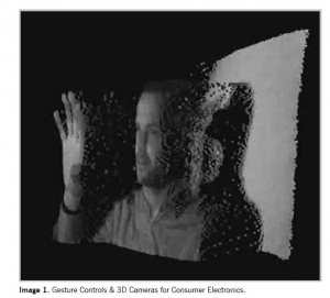
For a few years, diffractive optical elements (DOE) and microscanners have driven a large group of new products; mainly gesture controls and 3D cameras for consumer electronics (see Image 1), but also scanned lidars for machine vision and autonomous cars, as well as pico-projector scanners. For these new products, the combination of factors results in challenges for product safety and standardization. They are not intended as specialized professional products, such as lidars have been for the military, but are for consumer use. Therefore, in practice, they would need to be Class 1, Class 2 or Class 3R devices (depending on the wavelength range and country) but at the same time, for a satisfying performance in terms of detection distances, emission levels need to be relatively high. Because of the diverging or scanned nature of the emission, these systems suffer particularly from the conservative combination of classification rules of a 7-mm diameter pupil, an assumed exposure distance of 10 cm from the DOE or from the scanning mirror, together with an assumed accommodation to the apparent source at such short distance. While laser safety classification was always historically on the conservative side, it might be possible in the future to consider that the combination of those three exposure conditions is not only highly unlikely, but there are also reflexes (the near triad of accommodation) that result in pupil constriction when accommodating to a close target.

Defining measurement (pupil) diameters smaller than 7 mm for very close distances and as function of accommodation target might be a possible relaxation for future amendments, but would make the analysis even more complex. Also, possibly, emission limits can be raised somewhat in the higher nanosecond and lower microsecond regime, which is a task for the International Commission on Non-Ionizing Radiation Protection, ICNIRP to which the IEC refers for bio-effects committee work. Particularly for a change in the emission limits the general “predicament” exists that the injury thresholds depend in a very complex manner on wavelength, pulse duration and retinal spot size. When emission limits for products (or exposure limits for the eye) are to be made to reflect the thresholds more accurately to reduce needlessly large safety margins, it automatically makes the limits more complex since simple limits by default would be, for many scenarios, over-restrictive. One exception in the 2014 IEC and ANSI revision applied to small retinal sources, where it was possible to greatly simplify the analysis of pulsed emission by setting the multiple pulse correction factor CP (or C5) to unity, at the same time permitting significantly higher emission levels as compared to earlier editions. On the other hand, in the same revisions, the analysis of extended retinal images became more complex by permitting significantly higher emission levels for devices in the range of the lower “safe” classes.

Besides possible adjustments in the emission limits, two concepts based on engineering safety features are currently in development in the responsible standardization committee at IEC to permit higher emission levels for divergent or scanned systems – but still achieve classification as “safe” class, such as Class 1 for IR and Class 2 for visible emission.

The first is a virtual protective housing (VPH) where the emission is automatically reduced when an object enters the VPH. In such a device, one or more sensors monitor the protected volume. Outside of the protected volume, the emission needs to be below the limits for the class that is to be achieved, such as Class 1. When the VPH is free of relevant objects, the emission level within that volume can be higher: as long as human access to this radiation is prevented by the system, it is not relevant for product classification. The sensor system thus establishes a virtual protective housing instead of a real one, and defines what is referred to as the “closest point of human access”.

The second type of engineering measure to raise permitted emission levels applies to lasers mounted on vehicles and other moving platforms. When the vehicle is stationary, only normal emission levels are permitted. When the vehicle is at a certain speed, it can be assumed that another vehicle that is driving at the same speed will do so with a minimum distance. Thus the speed of the platform is the basis to define the closest point of human access that is to be considered for classification, which can, for instance, be 1 or 2 meters from the car with the laser.

Both types of engineering features have the advantage that the emission is tested against permitted levels at farther distances than usual, resulting in significant increases of the permitted emission level for diverging or scanned emission. While the IEC standard can already be interpreted in a way as to permit classification on engineering features that prevent human access, in order to assure international standardized testing conditions, it is necessary to update the IEC standard and provide specific performance requirements. For instance, for the virtual protective housing, it will be necessary to define probes used to test if the emission is reduced when an object enters the VPH. For the “moving platform” concept, it will be necessary to define the measurement distance as function of vehicle speed, as well as additional requirements to prevent that people on or in the vehicle have access to hazardous levels of laser radiation, such as when the laser is mounted on the roof of the car and there is a sunroof, or people on a pickup truck’s bed. A virtual protective housing might be needed to prevent access for these cases and to ensure that the concept of “moving platform” is internationally accepted for formal product classification. After all, it needs to be appreciated that classification of products following IEC 60825-1, as a basic principle, can only rely on engineering performance of the device and cannot depend on proper installation or behavior of the user.

**Several of the issues discussed in this article were also topics of ILSC 2017 papers, including the history of CDRH and IEC standards in invited presentations by Jerome Dennis and David Sliney, respectively, as well as the moving platform concept. The 2014 updates of IEC and ANSI standards were discussed in earlier ILSC papers.

Karl Schulmeister was project leader for the 3rd Edition of IEC 60825-1 and is a consultant on laser product safety at Seibersdorf Laboratories in Austria. For more information,
visit http://laser-led-lamp-safety.seibersdorf-laboratories.at.

Proposal of a New Laser Safety Guard Material & Its Protection Time Evaluation Method

KUNIHIKO WASHIO, TAKASHI KAYAHARA, YOSHIHIRO EMORI AND AKIRA FUJISAKI

Thin metallic sheets made of aluminum or steel with a thickness of 1 to 2 mm are often used as laser guard materials. However, metallic laser guards are easily penetrated by high power laser irradiation due to quick melting.

Therefore, their protection times are short. Current problems of metallic laser guards are: (1) A tendency toward generating a large through hole due to quick melting if irradiated with high-power laser; (2) Protection times are significantly influenced by surface reflectivity conditions and reflectivity changes over time.

Contrary to ordinary metals, pitch-type carbon fibers have desirable features such as non-melting, high-sublimation temperature and low-reflectivity. Therefore, we have conducted experiments to evaluate pitch-type CFRP (carbon-fiber reinforced plastics) as a new guard material for high-power lasers. These 3-mm thickness, lightweight CFRP plates incorporate industry grade pitch-type carbon fibers K13916 having tensile modulus of 760 GPa, fabricated by Mitsubishi Plastics Inc. The specific gravity is only 1.7. The CPRP plates consist of stacked multilayers with carbon fiber orientation orthogonal to each other, layer by layer. The carbon orientations of the top and bottom layers are designed to be in parallel. The fabricated CFRP plates have strong anisotropy in thermal conductivity: 60 W/(m•K) for X and Y directions vs. 1 W/(m•K) for Z direction. Therefore, the heat generated at the irradiated front surface is effectively prevented from reaching the rear side due to the very low thermal conductivity in Z direction.

Figure 1 shows the schematic diagram of experimental setup. A CW fiber laser capable of emitting up to about 10 kW at a wavelength of about 1,070 nm was used. The laser beam was irradiated at test samples with a focusing lens having focal length of 300 mm. The length L from the focal point to the test samples was adjusted so that the irradiated beam diameter becomes either 60 mm or 30 mm. Two silicon photodiodes PD10 and PD11, equipped with 50-nm bandwidth bandpass filters having different center wavelengths (1,075 nm and 1,000 nm, respectively), were used in the front side to differentiate scattered laser radiation and thermal radiation.

Figure 2 shows the layout of eight photodiodes located on the back plate inside the shielding box. Seven photodiodes from PD2 to PD8 are with bandpass filters having a 1,075 nm center wavelength. One photodiode PD12 is with a bandpass filter having 1,000 nm center-wavelength. All the photodiodes were used in photovoltaic mode without applying any bias voltage. The output waveforms from the photodiodes were simultaneously recorded with a 10-channel data logger. The input resistance of the data logger was set to be 2.4 kΩ.

Three different types of materials were used for test samples. They are: 3-mm-thickness CFRP, 1.6-mm-thickness zinc-coated steel and 1.5-mm-thickness aluminum. The top surfaces of aluminum test samples were gray coated to suppress strong reflection. Two types of sample-holding arrangements were used for test samples having two different sizes. One arrangement is for 300-mm-square, larger size samples and is designed to thermally insulate them from the shielding box to ensure natural air cooling. The other arrangement is for 150-mm-square, smaller-size samples and is designed to test small samples economically by utilizing partial and indirect peripheral cooling by attaching the sample to a rear-side panel having four watercooled heat sinks. Figure 3 shows pictures taken during and after laser irradiation for a 300-mm square, pitch-type CFRP test sample.

Table 1 shows the comparison of test results for partially and indirectly cooled, 150-mm-square test samples irradiated with 60-mm-diameter laser beam at 3 kW. Average values of experimentally measured penetration times for ten samples of 1.6-mm-thickness zinc-coated steel and 1.5-mm-thickness gray-coated aluminum were 55.89 s and 3.96 s, respectively. The relevant standard deviations were 3.13 s and 0.14 s, respectively. Penetrated large holes are clearly visible for metallic test samples. On the other hand, for the case of 3-mm-thickness pitch-type CFRP, we could not observe any penetration for all the tested ten samples, even after more than three minutes of irradiation, although slight texture and color change could be seen on the rear surfaces.

When pitch-type CFRP test samples were irradiated with laser beams having much higher irradiation densities, we could observe rising, but from complex signal waveforms from the photodiodes located inside the shielding box. To interpret photodiode signal waveforms, a small mirror was placed in the rear side to monitor the phenomena occurring on the rear surface. By comparing the video data and photodiode signal waveforms, we have found that rear-side ignition starts much earlier than the penetration, or burn-through. Therefore, we have decided to use this rear side ignition time, instead of penetration time, as the experimental limiting time-base for the statistical calculation of protection time.

Figure 4 shows an example of irradiation test results for 300-mmsquare, larger size, naturally air-cooled CFRP test samples, irradiated with 30 mm-diameter laser beam at 9 kW. The rear side ignition time has been measured to be 23.5 seconds for this sample. A tiny hole can be seen in the bottom picture for the rear surface. Figure 5 a shows histogram of rear-side ignition times observed for 300-mm-square, naturally-air-cooled ten test samples.

The average value of rear-side ignition time has been measures to be 24.89 s with standard deviation of 3.61 s. From these data, the protection time of 3-mm-thickness pitchtype CFRP plates for irradiation of 30 mm-diameter laser beam at 9 kW (power density of 1.27 kW/cm2) has been calculated to be 9.8 s, which is very close to satisfy T3 class condition of minimum inspection interval of 10 s according to IEC 60825-4 Ed. 2.2: 2011, Safety of laser products – Part 4: Laser guards.

In conclusion, it has been demonstrated that lightweight pitchtype CFRP plates (with density of about 1/4 of steel) can provide remarkably long protection time against multi-kW high power fiber laser irradiation when used as a passive laser guard. Pitchtype CFRP would be also useful as a key component material for construction of active laser guards. It must be pointed out here, however, that proper precautions against the flames and fumes generated at the irradiated front surfaces of pitch-type CFRP plates become necessary.

The authors greatly acknowledge funding of METI standardization project “International Standardization for Highly Laser-Resistant Laser Guards.” The authors also thank the committee member of OITDA on high strength laser guards for helpful and valuable discussions and encouragement. Kunihiko Washio is president of Paradigm Laser Research Ltd. Takashi Kayahara, Yoshihiro Emori, and Akira Fujisaki are engineers at Furukawa Electric CO. LTD.

Laser Institute of America’s Executive Director Peter Baker Retires After Decades in the Industry

Retirement comes after more than 28 years of leadership at LIA

ORLANDO, FL (PRWEB) JUNE 12, 2017

Laser Institute of America (LIA) Executive Director Peter Baker officially retired from his position on May 1 after decades at the organization’s helm.

Executive Director Peter Baker’s retirement comes after more than 28 years of leadership at LIA.

Baker’s initial experience with LIA was as a speaker at its very first conference for materials processing in 1980. He was elected as LIA’s executive director at the 5th ICALEO® in 1988. Baker and his wife, Sunny, opened the Orlando office in April of 1989.

Noting that Baker served LIA for more than half of its existence, LIA’s 2017 President Paul Denney wrote in the March/April issue of LIA TODAY that within that time frame, Baker “has taken an organization that consisted of a handful of academics and engineers to an organization that is recognized as a world-leading society for laser safety and applied laser technology.”

Denney admits that finding “the next Peter Baker” will be no easy feat, and he is hard at work with the Selection Committee trying to secure the right leader for LIA’s vision. During the transition, Baker will be available to help guide the new executive director in the role, and LIA will continue to benefit from his mentorship.

At the end of 2016, Baker was the first recipient of LIA’s Leadership Award, which was designed to highlight an individual who exhibited outstanding leadership in an organization and who significantly benefited the laser industry. Going forward, the award will be named after him, signifying his profound worldwide impact and advancement in laser sciences and applications.

After more than 28 years with LIA, Baker says he is extremely grateful to have worked with various members, presenters, instructors, and staff. By the same token, his years of business, leadership, and management experience have not gone unnoticed by LIA.

“I can’t even begin to express the impact that Peter has had during his time with LIA—not only in the expertise and leadership he brought, but also regarding growth in my own career. I know he has impacted countless others here at LIA over the years as well,” said Jim Naugle, LIA’s Marketing Director. “I wish him the best and will definitely miss his presence and direction here at LIA.”

Baker’s unique experience and background allowed him to bridge the technical and business communities that make up the laser industry, guiding LIA to a position that supports laser safety and applications in manufacturing, R&D, medicine, and education. He leaves LIA as a viable organization that is primed and ready to grow with the changing economic climate.

About LIA

The Laser Institute of America (LIA) is the professional society for laser applications and safety serving the industrial, educational, medical, research and government communities throughout the world since 1968. http://www.lia.org, 13501 Ingenuity Drive, Ste 128, Orlando, FL 32826, +1.407.380.1553.

Laser Institute of America Announces Session on North American Additive Manufacturing as Part of Lasers in Manufacturing 2017 Event

LIA will hold a session at LiM 2017 in Munich, Germany to offer unique perspective on how North American laser companies are successfully using additive manufacturing technology.

The Laser Institute of America (LIA) will organize for the first time a 1.5 hour Additive Manufacturing (AM) session called AM: Trends in North America as part of the World of PhotonicsCongress LiM 2017 event.

Held on Wednesday, June 28, 2017, from 2:00-3:30 PM local time at the International Congress Center in Munich, Germany, the event runs as a session of a subconference of the larger LiM event from June 26-29, 2017. LiM is a scientific conference on the latest advances and future trends in the field of laser materials processing, with a focus on potential for industrial applications. Organized by the German Scientific Laser Society (WLT), LiM 2017 is the premier international forum for researchers and experts in laser manufacturing.

The unprecedented AM session offered by LIA is intended to provide updates on the most current laser additive manufacturing applications and offer a helpful perspective regarding how American and Canadian companies are successfully using AM technology to reduce cost and increase efficiency.

“Now is an important time to be a part of all that is developing in the AM world in North America,” said Jim Naugle, LIA’s Marketing Director. “We are pleased to add our knowledge and insight to the vast body of additive manufacturing expertise offered at LiM 2017 through the AM: Trends in North America session.”

Attendees will include engineers, manufacturing managers, system integrators, precision parts specialists, and OEMs from all over the world in fields such as business development, manufacturing, construction, and design.

Featured Keynote David Ott from the Global Humanitarian Lab (GHL) will explain how 3D Printing can bring together the humanitarian world (private, academic and scientific) to address common challenges in disaster affected communities.

Other invited speakers include Rob Martinsen, CTO of nLight, and William Herbert, Director of Corporate Development for Carpenter Technologies. Martinsen will speak of breakthrough solutions for additive manufacturing and Herbert will cover material requirements. The session will come to a conclusion with presenter Yannick Lafue, Business Developer for Aeronautics, Defense and Oil & Gas at IREPA LASER with his presentation on AM with LMD-CLAD process: an Industrial opportunity.

For more information on this event, including sponsorship information, please contact marketing@lia.org or +1-407-380-1553. To learn more about LiM 2017, visit the LiM 2017 website.

View the PRWeb release here

Board of Laser Safety Announces Revised Certified Laser Safety Officer Exam to Begin in March 2017

All CLSO exam questions reviewed for clarity and ANSI Z136.1-2014 Safe Use of Lasers standard compliance

For Immediate Release

ORLANDO, FL – The Board of Laser Safety (BLS) announces today that its Certified Laser Safety Officer (CLSO) exam is now revised to comply with the ANSI Z136.1 Safe Use of Lasers standard, 2014 edition. The CLSO exam is intended for all non-medical laser safety officers and is administered by the BLS.

The first in-person offering of the revised exam will take place on Sunday, March 19, at the Sheraton Atlanta Airport, the day before the official start of the 2017 International Laser Safety Conference (ILSC®). In addition to the March 19 exam preceding ILSC, future in-person opportunities to take the exam include June 9 in Denver, CO, and September 22 in Chicago, IL. The revised CLSO exam is also available via computer-based testing in the U.S. and Canada through PSI Comira.

“All questions on the revised exam have been reviewed by a team of subject-matter experts and are now presented more clearly and concisely so candidates can focus on the content of the question rather than how it is worded,” said Barbara Sams, BLS Executive Director.

Now is the time to register to take the newly revised CLSO exam to remain competitive in the field. Interested candidates are advised to contact the BLS office with any additional questions regarding the exam at +1.407.985.3810 or bls@lasersafety.org.

——–
About Board of Laser Safety

The Board of Laser Safety (BLS) is a non-profit organization affiliated with Laser Institute of America (LIA) and dedicated to the improvement in the practice of laser safety by providing opportunities for the education, assessment and recognition of laser safety professionals. To learn more about BLS and their certification opportunities for medical and non-medical laser safety professionals, please visit http://www.lasersafety.org.

About LIA

The Laser Institute of America (LIA) is the professional society for laser applications and safety serving the industrial, educational, medical, research and government communities throughout the world since 1968. http://www.lia.org, 13501 Ingenuity Drive, Ste 128, Orlando, FL 32826, +1.407.380.1553.