Whether you are an expert in the field of laser manufacturing, an ambitious student, or are just beginning your career, discovering new information about laser manufacturing applications is always a valuable endeavor.
3D Laser Cutting – Trumpf Inc.
With that in mind, the LIA team compiled a list of the top laser welding and manufacturing-related online publications for you to explore. These resources are packed full of information, tips, stories, and real-life applications for all laser manufacturing levels.
Tulsa Welding School has served as a training school for welders for over 60 years. With three locations nationwide, Tulsa Welding School is focused on the education and careers of its students. Beyond classroom and hands-on instruction, the institution regularly updates The Welding School Blog and covers the most breaking information in laser welding, like this article on how new technology, including lasers, is revolutionizing the welding industry.
Other posts focus on potential students and individuals interested in the field, or aim content toward current professionals, discussing competitions, career advice, and networking opportunities for welders. In all, the Welding School Blog manages to share intriguing stories, history, and background on the history and impact of welding applications.
Read more from The Welding School Blog on laser technologies in welding here.
Industrial Laser Solutions for Manufacturing is an online magazine packed full of relevant content for laser manufacturing professionals. Although the magazine itself is released every other month, the Industrial Laser Solutions for Manufacturing web page is frequently updated with the latest news, developments, and information— including laser engraving and welding.
Featuring industry news, relevant videos, popular products, financial reports, and links to other online resources, this publication is bookmark-worthy for anyone professionally involved with laser manufacturing. Be sure to check out the Editor’s picks for exclusive pieces not found in the magazine.
Like the previous entry, Industrial Photonics Magazine is also an online industry magazine. This magazine does an excellent job of aggregating the best news, features, webcasts, videos, and more in relation to laser applications. While you will find a whole lot more than pieces on laser manufacturing, Industrial Photonics Magazine stays on top of the latest industrial headlines, making it a valuable resource for those looking to expand their laser knowledge even outside of their own profession. Read on and subscribe by clicking here.
Laser Institute of America is committed to providing the latest and most valuable laser manufacturing information to our members and the laser manufacturing community at large. For breaking industry news and updates in one convenient location, visit our website LasersToday.com here. You can even sign up to receive updates directly to your inbox, so you never miss articles on Laser Weld Process Monitoring and Laser Welding Publications, for example.
LIA Today is a full-color newsletter that is published six times per year. It includes articles on the latest industry news to keep members and other laser professionals current on important issues that impact the laser community. To read the September/October issue of LIA today, Science and Research, and to subscribe, click here.
Be sure to support the blogs listed above by clicking through the links – and feel free to comment below and let us know what your favorite laser manufacturing publications and resources are, too.
Become part of the LIA experience and stay on top of your laser manufacturing career. Explore how to become an LIA member today by clicking here.
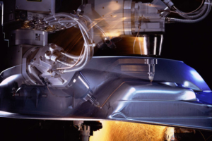
The economic case for using lasers in industrial welding applications is no longer in question. Industrial lasers provide massive leverage in the form of an unmatched combination of speed, precision, robustness and—increasingly—accessibility. In serial production they can provide time and cost savings, and enable more efficient product designs. The price per kilowatt of laser power has dropped steeply in recent years, and in combination with a growing market and increasing number of players supplying laser solutions, this has led to increasing commoditization of laser sources and systems. In the quest to gain an edge over the competition, many system integrators and manufacturers are shifting their focus to increasingly sophisticated sensing techniques in order to wring more performance and higher quality out of their laser processes.
Controls and checks are of course an integral part of any production chain. The cost of out-of-spec parts reaching the hands of end users can be incalculable, and may be more than monetary where safety-critical components are involved. Many excellent quality assurance measures applicable to laser welding have existed for decades. The gamut of checks that can be applied to ensure a weld result is good reaches upstream to production of the feedstock and downstream to a point where the weld may be part of a complex and expensive sub-assembly. What checks give the best return on investment for a manufacturer? This is a tough question to answer generally, but recent weld process monitoring advances have recently opened new opportunities for automated quality assurance and active control—improving laser weld quality and increasing certainty in the results.
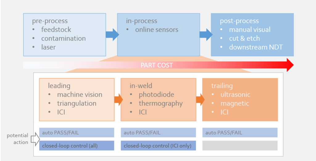
Laser welding checks can be loosely sorted into three subsets: pre-process, in-process and post-process. For now, we’ll use ‘in-process’ checks to refer to any automated measures deployed during the welding process (while the laser is on) but not necessarily measuring the process itself (where the laser hits the metal).
Pre-process checks include steps taken at any stage prior to welding to ensure welds turn out in-spec. Tight control of feedstock and supplier processes are employed to enforce adherence to material standards, but such approaches classically have rapidly diminishing returns on investment and may be outside of a given organization’s power to control. The output of the laser system itself may be monitored with power meters and beam profilers to ensure correct delivery of power to the workpiece. Some sophisticated laser systems tightly integrate laser power delivery with robot motion to further reduce potential process errors.
It’s a generally sound philosophy to try to predict and design out problems rather than react to them, but pre-process checks can’t stand alone. No pre-process measurement can capture all the variables that may influence results, so verification of the results of the process is essential.
Tried-and-true post-process inspection methods such as manual visual surface inspection and destructive testing are still favorites of many laser users who favor their intuitiveness and robustness. Challenges arise due to time, cost and expense, however. Visual inspection provides limited information, and the best measurements from destructive testing can only be practically obtained from a small fraction of finished welds; sometimes at an enormous cost in labor, scrap and lost production.
Automated post-process non-destructive testing exists in the form of x-ray CT, ultrasound and magnetic flux leakage. X-ray builds up highly detailed three-dimensional images of finished welds, including subsurface features, but is too expensive and time-consuming for all but the most specialized applications. EMAT ultrasound uses electromagnetic coupling to both produce and detect an ultrasound source inside ferrous materials. Magnetic flux leakage detects subsurface defects by measuring regions in which magnetic field lines “leak” out of the part as they skirt around voids in the material.
With downstream post-process checks, the most complete information (from sectioning and CT) is also the most difficult to obtain. Destructive testing can only be used on a small fraction of parts, none of which are serviceable after the fact. As an added complication, the further downstream the check is performed, the higher the value of the scrapped parts when defects are found.
A good balance of time and cost savings is found by concentrating checks in-process, using automated sensing equipment. In-process checks can also be sorted into pre- in- and post-weld groupings. In this case the leading (pre) and trailing (post) measurements happen close to the welding process, typically while the welding beam is on. Some in-weld measurements look directly at the point of contact between the welding beam and the material in order to directly sense process dynamics as they unfold.
Sensors that lead the process during welding carry an advantage over earlier pre-process checks in that they are placed at a confluence of weld quality pre-determinants. These sensors can catch errors caused by stock tolerances and fit-up, fixturing and motion control, often with the same measurement. Examples of this kind of sensor include laser triangulation and camera-based systems for seam following. The position of the seam is used in a feedback loop to correct the weld path on the fly.
Trailing sensors allow the finished weld to be assessed before any further value is added to the part, avoiding expensive scrap further downstream. Both ultrasound and magnetic flux leakage are good candidates for immediate, on-line inspection. Laser triangulation is also a popular choice to measure surface topography of the finished weld bead.
For measurement of the process itself, relatively few sensing options exist. The weld process produces intense light across a wide region of the spectrum, blinding traditional cameras without specialized filters. Photodiode sensors make use of these emissions by measuring different bands of optical radiation from the process zone; backscattered light from the welding laser, radiation from the weld plume, or blackbody emissions from the melt region can all be used to assess the weld process. The challenge when implementing these indirect measurements lies in determining which signals correspond to an in-spec weld. The teach-in process for such sensors typically involves lengthy comparisons with destructive testing, and once this stage is complete, the process conditions must remain stable for the sensor to function properly. The relationship between the light coming from process and the shape of the finished weld is complicated.
Thermography is another in-process sensing method that maps the distribution of heat on the surface of the melt pool and weld seam, in order to draw conclusions about subsurface features (e.g., fusion in a lap joint).
Indirect measurements are a useful litmus test for determining whether a process is behaving consistently, but they have their limits. The data often doesn’t provide enough to detail to point to a specific failure mode, or to control process parameters in response to measurements.
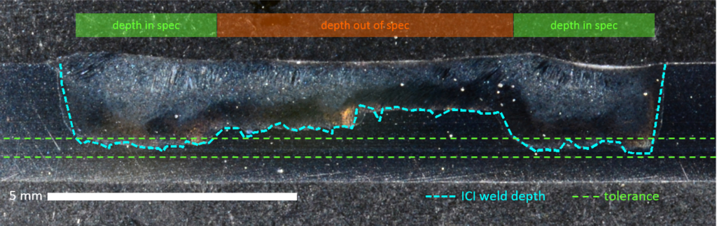
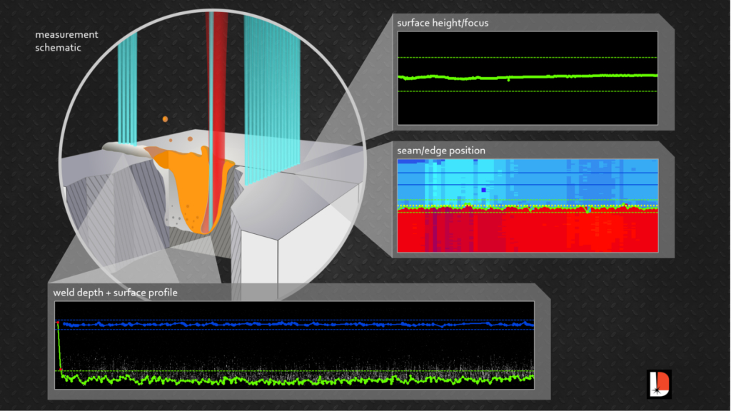
Inline coherent imaging (ICI), an emerging in-process measurement technology patented by Laser Depth Dynamics, measures weld penetration directly at the point where the process laser interacts with the workpiece. This technology is natively compatible with select modern welding heads (e.g., Laser Mechanisms FiberWELD), and retrofits are possible with most common fixed-optic and some scanning-optic heads. ICI makes a time-of-flight measurement with a secondary low-power laser beam, which is immune to blinding by the intense light radiating from the process. This beam is delivered through the same optics as the welding laser, allowing ICI to make direct measurements of the bottom surface of the vapor channel opened by the process laser. This translates into a direct weld penetration measurement. The information produced is similar to the outputs from destructive analysis. Since the measurement occurs during the weld, ICI can be used for automated pass/fail, or even to control the laser power in real time to reach a target depth.
A sectional weld micrograph with ICI penetration depth measurements
ICI also functions as a leading and trailing in-process measurement. Using a small pair of scanners on the head, the ICI beam can be moved to other regions of the workpiece. This allows collection of seam position and workpiece height data ahead of the welding beam, and imaging of the finished seam surface immediately behind the melt pool. All of these measurements are taken through the head optics, within a few millimeters of the process beam. This suite of quality checks can be performed by a single instrument, by rapidly switching between measurement positions during the weld. The end result is automated pass/fail on any combination of seam position, material height, keyhole depth and finished weld surface, as well as the option to run closed-loop control of laser power and robot motion using the former three measurements. ICI technology provides the most complete automated laser weld monitoring solution to date.
Significant time and cost savings can be realized with advanced in-process sensing. The latest generation of monitoring technology eliminates the need for some downstream tests. The quality assurance for a given weld can often be worked into the existing cycle time. Scrap rates can be cut down through dramatic reduction of destructive tests. Inspection of 100 percent of production welds means entire batches don’t have to fail when defects are discovered, and the direct nature of latest-generation process measurements lowers the theoretical likelihood of false positives when compared with indirect approaches.
ICI can be used to monitor multiple aspects of the laser weld process at the same time
The ability to keep a complete, accurate record of production parts is allowing manufacturers to change how they approach quality assurance. It’s now possible to think weld-by-weld instead of batch-by-batch, with unprecedented confidence in the quality of the finished product.
Chris Galbraith is the Applications Specialist and Paul Webster is CTO at Laser Depth Dynamics Inc.20
Conference’s diverse program instructed shops and industry professionals in how to leverage lasers to revolutionize manufacturing processes
FOR IMMEDIATE RELEASE
ORLANDO, FL (PRWEB) SEPTEMBER 30, 2016
Laser Institute of America held its first Industrial Laser Conference on Tuesday, September 13, 2016 at the International Manufacturing Technology Show in Chicago. Tailored exclusively to the future-forward industrial manufacturing professional, the conference showcased leading laser applications driving the evolution of manufacturing, and instructed manufacturing shops and industry professionals in how to leverage lasers into their manufacturing processes in a high-demand marketplace.
Thirteen experts in laser manufacturing, including technical directors, laser applications engineers, and program managers, presented a diverse program in room W190-A of Chicago’s renowned McCormick Place. Hailing from leading manufacturing organizations such as IPG Photonics Corporation, SLM Solutions NA, Inc., TRUMPF Inc., FANUC America Corporation, Laserline Inc., Optomec Inc., Lincoln Electric Company, Fraunhofer USA – CLA, Alabama Laser, Mitsui Seiki (U.S.A.), Inc., and Imperial Machine & Tool Co., the presenters covered topics like technology advances in additive manufacturing, hybrid additive and subtractive tool technology, laser additive manufacturing in production, advances in welding with fiber lasers and novel beam delivery products, and the role of flexibility in laser automation.
These innovative techniques are emerging and revolutionizing the industry to meet market demands, all rooted in the field’s collective understanding of conventional machining. From advancements in technology to expected challenges, the LIA’s Industrial Laser Conference provided a newfound clarity on the present and future of industrial manufacturing.
“LIA was proud to deliver an elite lineup of laser experts in our first year of the Industrial Laser Conference, covering 360 degrees of lasers-in-manufacturing technology,” said Jim Naugle, LIA’s Marketing Director. “The opportunity to dive into a real machine shop’s journey into metal additive manufacturing with lasers and cover new innovations in directed energy deposition (DED) systems in one day, all while
receiving access to cutting edge exhibitions at the IMTS show, is a thrilling opportunity for manufacturing engineers, automation specialists, and sales managers.”
From seasoned manufacturing experts new to lasers, to shops who have already begun reaping the benefits of laser technology, the conference offered something for everyone in the sector, including James Hail of L-3 Communications. “[The show provided] excellent information! I learned a lot,” Hail said.
Attendees like Mansour Ashtiani of Huf North America hope to attend the event again. “It was a very professionally done conference,” Ashtiani said.
The Laser Institute of America (LIA) is the international society for laser applications and safety. For more information about the Industrial Laser Conference, including presenters, programs, and sponsor information, please visit http://www.lia.org/laserconference.
About LIA
The Laser Institute of America (LIA) is the professional society for laser applications and safety serving the industrial, educational, medical, research and government communities throughout the world since 1968. http://www.lia.org, 13501 Ingenuity Drive, Ste 128, Orlando, FL 32826, +1.407.380.1553.
Wayne Trail, a subsidiary of Lincoln Electric, is a leader in the design of flexible, automated systems utilized within a wide range of metal forming, fabricating and joining industries. Its current market segments include robotics, welding and fixturing; press automation; tube bending and fabricating systems; tubular hydroform and structural frame automation; build-to-print manufacturing services; and laser processing systems.
At the time of Wayne Trail’s inception, the company provided the Dayton, Ohio-region automotive industry with tools, dies and fixtures. The company’s reputation and customer base grew throughout the years, allowing for the development of its engineering expertise and inclusion of automation through the production of automated tube-bending systems. In addition, Wayne Trail acquired companies, such as Livernois Press Automation, Flexible Systems Engineering and VIL Laser Systems, which added to its visibility within the industry, expanding its capabilities and, ultimately, leading to its acquisition by Lincoln Electric in 2012.
Since then, Wayne Trail has added to Lincoln Electric’s strength by not only incorporating the staff’s experience in design and system building, but also in adding their proven capabilities and success in laser welding systems. Lincoln Electric employs over 10,000 people globally among their 49 manufacturing operations, joint ventures and alliances in 19 countries, with 180 employees located at the Wayne Trail facility. As laser experts, Wayne Trail has added to Lincoln Electric’s vast product line for numerous industries and products, such as automotive and specialty powertrain component systems and both standard- and custom-designed cells for laser welding, cutting, brazing and more.
Despite its numerous innovative offerings, Wayne Trail’s laser welding system services prove among its most important. From the automotive and aerospace sectors to the battery and energy sectors, Wayne Trail continuously meets new challenges through their powertrain laser systems, multiple robotic laser cutting systems, laser ablation and brazing systems. The company adds to Lincoln Electric’s history as a leading global innovator, continuing to invest in research and development of laser processes – including brazing, ablation, laser die cleaning and laser/hot wire for cladding and welding applications – which hold the potential to help move technology further around the globe.
Over the last five years, Lincoln Electric has grown in automotive, aerospace and commercial system applications for multi-axis laser processing. Continued development in technology and the increase in reliability has allowed lasers to venture from the lab into real-world production systems. As lasers continue to prove themselves as a reliable method of joining and cutting of numerous materials within the industry, immense growth has occurred, creating new jobs and allowing for Lincoln Electric’s expansion into other areas of automation requirements.
With the availability of new materials and affordability of laser technology for customers, Lincoln Electric continues to weld, clean, cut and drill complex components for customers. To meet customers’ developing demands, Lincoln Electric’s engineering groups remain dedicated to developing and advancing innovative system concepts and tools. This was seen when Wayne Trail R&D engineers raised deposition rates and eliminated waste powder while using powder systems through the development of a hot wire process.
As a member of Laser Institute of America (LIA) since 1995, Wayne Trail has been able to maintain access to information and opportunities that span all laser-related industries. It has also allowed the company to collaborate and contribute to the industries it supports, through a presence at LIA conferences and expos, while also keeping Lincoln Electric close to the industry and helping it witness the growth of the laser.
Introduction An additive manufacturing method developed by TWI within the framework of an EU-funded project could drastically reduce component manufacturing times.
TWI engineers have been using laser metal deposition (LMD) to produce net shape thin-walled engine casings, aiming to reduce the environmental impact of civil aerospace manufacturing.
In LMD, a weld track is formed using metal powder as a filler material which is fed, through a coaxial nozzle, to a melt pool created by a focused high-power laser beam. An inert gas carrier transports and focuses the powder into a small area in the vicinity of the laser beam focus (powder-gas beam focus). By traversing both the nozzle and laser, a new material layer develops with good precision and user-defined properties. The application of multi-layering techniques allows 3D structures to be created directly from a CAD model without the need of additional tooling. Historically, coatings and 3D objects deposited by LMD tend to be considered as near net shape.
The focus of the study was an axis-symmetric cylindrical casing with a maximum diameter of 300 mm, a wall thickness of 0.8 mm and a height of 88 mm (see Figure 1). The component is traditionally manufactured from a nickel alloy (Inconel 718), forming a complex geometrical topography requiring specialist tooling, all of which absorbs significant resource (six months lead time) and generates a large amount of waste material when manufactured.
Figure 1
From Design to Manufacture Two years of development and six months of demonstration activity, led by the team at TWI’s Technology Centre in South Yorkshire, concluded the validation of CAM-style software tools created as a plug in to TWI’s ToolCLAD software: a software package being developed at TWI specifically for the LMD CAD-to-part-manufacturing process. The plug in maps a five-axis vector toolpath with deposition parameters to guide a three-axis coaxial LMD nozzle across a moving substrate manipulated by a two-axis CNC rotary table, creating a novel method of LMD manufacturing.
With precise synchronization of the movements of rotation and tilt of the substrate with incremental movements of the coaxial nozzle (predominantly in the +Z direction), a continuous spiraling weld track can be deposited or ‘grown,’ layer on layer, from out of the substrate. The helical multi-layering technique allows a thin-walled 3D contour to form, which accurately follows the changing directions of the original CAD surface profile (STL file). The process is analogous to a clay pot forming on a potter’s wheel. By allowing the substrate to control movement, rather than traversing the nozzle around a circular path, gives a consistent and regular weld track, and therefore, a good surface finish. Furthermore, the tipping of the substrate to axially align the orientation of the growing wall with the cladding nozzle allows overhanging features to be created without the need to build additional support structures.
A key innovation was the development and use of an adaptive slicing algorithm which automatically varies the numerical slice height (lead distance or pitch) between each helical revolution of the calculated tool path. The magnitude of the change is governed by the orientation of the facet (triangle) normal at the required slice height within the STL CAD model. However, during deposition, the actual build height is maintained at a fixed value to ensure a consistent surface quality. Hence, the adaptive slicing approach modulates the number of layers deposited per unit distance of build height which is governed by the tilt angle of the rotary table. Without this feature, printed parts would have a sizing error in the Z direction.
Modelling Heat Effects to Improve Precision To assist with the experimental investigations the heat effects during LMD processing were replicated by Finite Element Analysis (FEA). With the utilization of FEA models, the prediction of the shape change of the LMD built casing could be calculated and compared to the target CAD geometry. The results from modelling agreed closely with visual observations, where much of the temperature dependent distortion occurred in the first 15-20 mm of build height. This caused the cylindrical wall to pull inwards. This distortion is linked to the build-up of cylindrical stress distributions during cooling coupled with the thermal shock of depositing the wall onto a substrate held at room temperature. The calculation of the magnitude of the distortion, layer on layer, helped to compensate the wall movement and maintain nozzle alignment on top of the growing wall through appropriate adjustment of the tool path.
Bringing Real-World Benefits The high integrity of the final part, coupled with the low thermal loading imparted by the process, allowed it to be removed from the substrate with little further distortion. This is evident from the results of geometric 3D scanning. Overall tolerance across the largest diameter was ±250 µ. The wall thickness averaged 0.854 mm with a tolerance of 0.8 mm ±0.1 mm. The surface finish averaged 15-20 µ RA with the higher values centered on the fillet radii; probably because the powder-gas beam focus was not co-located directly on top of the growing wall during continuous reorientation of the table. This created a subtle stair step effect around a curved feature. It is important to note that a final heat treatment step would be necessary to alleviate residual stress that invariably builds up during LMD manufacture.
The LMD manufacture and subsequent dimensional measurement of a combustion casing prototype confirmed that the software and procedures developed in this study were capable of net shape manufacture. Furthermore, the LMD part was proven to have the same geometrical accuracy as a part produced by conventional manufacturing methods. The only difference was surface roughness, which increased from 0.8-1.6 µm to 15-20 µm in the LMD part; although this was still considered acceptable.
The key to the success of achieving the required geometric accuracy and surface finish was minimizing nozzle movement and allowing the substrate to do most of the work. The 7.5 hr build time was a significant reduction over the current six month lead time. However, the LMD productivity rate of 0.1 Kg/hr of deposited powder was considered very low. This can be ascribed to the requirement of wall thickness and surface finish which dictated weld track size and quality. The density of the final part was at least 99.5 percent. The weight of powder material fused in the final part was 750 g and 1.1 Kg of powder was pushed through the nozzle during manufacture, giving a 70 percent material efficiency. Conventional manufacturing routes for the casing (including the manufacture of tooling) generated several 10’s Kg of waste material.
The presented work is now being applied to other demonstrator applications across a range of different industrial sectors. This includes procedures to manufacture geometries with thicker walls, the addition of surface deposited features and parts with larger diameters.
Dr. Carl Hauser is a consultant on Additive Manufacturing and 3D Printing for TWI and would like to thank Neil Preece (TWI, UK) and Loucas Papadakis and Andreas Loizou (Frederick University, Cyprus) for assisting in the experimental work and process modelling.