Evaluation Of 3D-Printed Parts By Means Of High-Performance Computer Tomography

By: Elena Lopez1, Tomás Felgueiras1, Christian Grunert1, Frank Brückner1, Mirko Riede1, André Seidel1,2, Axel Marquardt2, Christoph Leyens1,2, Eckhard Beyer1,2

1 Fraunhofer Institute for Material and Beam Technology, Winterbergstraße 28, 01277 Dresden, Germany

2Dresden University of Technology, 01062 Dresden, Germany

Introduction

Qualification and certification of parts made by AM processes has been identified by various authors [1, 2, 3, 4, 5] as one of the main challenges for the widespread adoption of AM in fabrication of structurally critical components. Traditionally, the qualification of parts is made by extensive non-destructive and destructive tests in a representative sample amount of the final product. This is a slow and expensive process in any kind of production, but in AM processes, it also contradicts many of the identified advantages, i. e. potential to save material and therefore process costs. To solve this problem, the qualification of AM parts demands a different approach, with focus in the research of certification of AM parts based on design and correlations of parameters during manufacturing and non-destructive tests [1, 4, 5]. This is attained through standards that are emerging to control key process factors and ensure uniformity and consistency across multiple machines and manufacturers. These standards are quite recent and started being published in 2013, with new actualizations appearing every year, in an effort of ASTM and ISO organizations to keep up with the fast paced development of AM technologies [1, 4, 5]. However, indirect methods such as build planning and process monitoring need further development to be broadly applied as a certification tool, which, for the time being, leaves final part qualification as the only way to warrant quality.

Due to the unique capability of AM technologies of making parts with complex geometrical forms and internal features, it is necessary to employ inspection methods that are capable of assessing part quality as a whole. Therefore, non-contact methods are the most promising tools to analyze AM parts,  X-ray computer tomography (CT) and 3D scanning being the most prominent ones.

Within this paper the use of computer tomography for quality control of final parts was explored, with the geometrical complex demonstrator developed by Fraunhofer IWS as a test part. First, CT was used to explore process limitations of electron beam melting (EBM) to produce geometrically accurate parts. Second, different demonstrators made by selective laser melting (SLM) with different materials were also compared in terms of geometrical accuracy and finally, comparison of the CT with 3D scanning measurements were carried out and analyzed for the different demonstrators.

Experimental: Inspection techniques

X-ray computer tomography (CT)

X-ray computer tomography (CT) uses electrically generated high intensity X-rays that pass through the investigated object from different angles as schematic represented in Figure 1. As X-rays pass through the  object, they are attenuated due to absorption or scattering, generating different grey values. The total attenuation depends on the material composition, density and object thickness. The remaining X-ray fraction is registered by the detector generating hundreds or thousands of cross-sectional projections which are stacked together. Through mathematical algorithms, 3D voxels are created (3D pixel analog, with the associated grey value) which form the 3D reconstruction of the object.

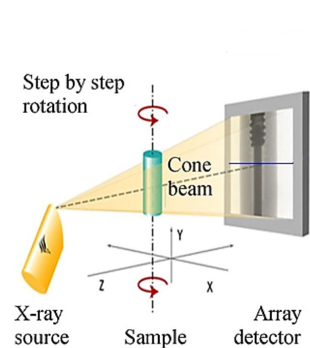
Figure 1 – Computer tomography working principle


CT enables the scanning of all surfaces of an object, even if they are inside a part (e.g. cooling channels) because of the nature of X-ray. This results in a fully digitized object that allows a qualitative and quantitative characterization of the investigated object, giving exact information about the total part volume and wall thickness as well as porosities, cracks and inclusions [6].

The set-up used for the experimental work in this paper was a YXLON FF35 CT equipped with a 250 kV reflection X-ray vacuum tube with minimum spot size of ≤6 µm. In terms of detection, a 1792×2176 pixel YXLON flat panel 2530 detector was used.

3D Scanning

3D scanning uses structured light, i.e. a laser, that is projected on to the object which will distort the light direction depending on its shape.  The light is captured by the camera and through triangulation the location of the measured point is calculated (see Figure 2). These points are afterwards processed by an algorithm and a 3D rendering of the object is made [7, 8].

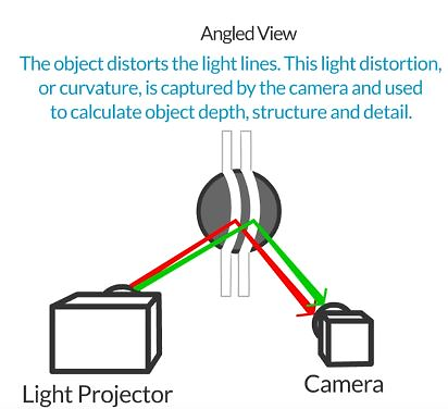
Figure 2 – Working mechanism of structured light 3D scanner devices.


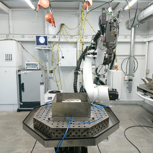
In the work presented in this paper, a GOM ATOS Core 45 was used (Figure 3) based in stereo fringe projection. In addition, it employs two cameras and a projector, that allows the capture of the object’s full surface geometry through a dense point cloud or polygon mesh[9].

Figure 3 – 3D scanner: GOM ATOS Core 45.


Demonstrators

The use of demonstrators with defined complex geometrical features provide a proper way to evaluate the performance and benchmark of different AM techniques in order to determine process and geometrical accuracy, process repeatability and surface finish. The demonstrators in this paper are designed with challenging geometrical features with different sizes, like overhangs and thin wall structures. Different authors [10, 11, 12] proposed many different demonstrator designs, but some challenging geometrical features like internal channels have not been considered so far. The considered geometrical features at Fraunhofer IWS are detailed in Figure 4 and Figure 5 (see also Table 1). The demonstrator was also designed in a way that a scaling-up will ensure the comparison for Laser Metal Deposition.

Table 1 – Geometrical features extracted from the demonstrator and their quantification with suitable test methods.


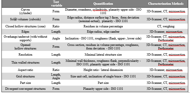
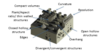
Figure 4 – Defined demonstrator to evaluate different challenging geometrical features (see description).

Experimental Results and Discussion

Demonstrator Analysis

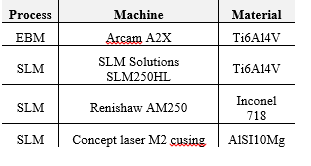
Several demonstrators made by different AM techniques were analyzed, as shown in Table 2. The analysis was made through X-ray computer tomography equipment YXLON FF35 CT, with the reconstruction software YXLON Reconspooler version 1.2.1.0 and the software VGStudio MAX 3.0 for the nominal/actual comparison and porosity analysis.

Table 2- Processes, machines and materials used for the building up of demonstrators.

EBM Demonstrators

On the analysis of the EBM parts, four demonstrators were considered. They were built with the same parameters (Table 3) but different support base square grid sizes as shown in Figure 5).

Table 3 – Build parameters of the EBM demonstrators.

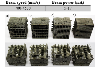
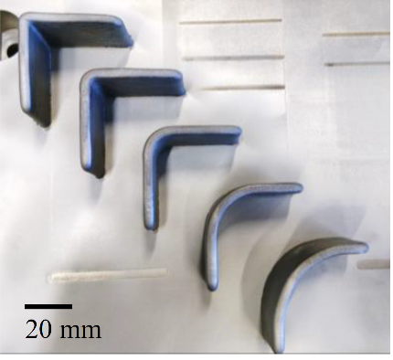
Figure 5 – EBM Ti6Al4V demonstrators with different square base sizes: a) 6x6mm square size; b) 5x5mm square size; c) 4x4mm square size; d) 3x3mm square size.

The EBM demonstrators did not accurately reproduce the features proposed originally, since they suffered from swelling on the Z direction, distorting the overall part (Figure 6).  This defect indicates that high beam energies of 300 J/m and above were used [13]. Adding to the swelling in the Z direction the demonstrator also suffered from retraction around the part and the excessive building temperature led to sintering of powder inside the internal channels.

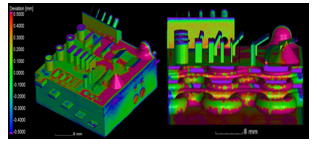
Figure 6 – Left: EBM demonstrator 6x6mm comparison at ±0,5mm deviation with the CAD file. Right: Perpendicular cut of the EBM demonstrator 6x6mm with comparison at ±0,5mm deviation with the CAD file, where the deviation of the channels can be observed

Comparison of deviation percentage of EBM demonstrators at different tolerance distances (Figure 7) revealed a positive effect of smaller square grid size, promoting higher heat transfer part/base, resulting in less distortion. However, even at ±1 mm deviation the demonstrators didn’t reach an ideal minimum threshold of 10% deviation. The 6x6mm demonstrator displayed the highest distortion visually, though displaying slightly best results at ±0.1 mm and ±1 mm tolerance (85.8 and 32.8%). This effect might be due to the automatic registration of the part made on VGstudio MAX which will tend to decrease the deviation between part and CAD file achieving a best fit.

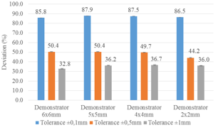
Figure 7 – Deviation of EBM demonstrators at different tolerances.

SLM demonstrators

Three different materials have been chosen for the manufacturing of the SLM demonstrators (Ti6Al4V, Inconel 718 and AlSi10Mg). These materials have been selected due to their relevance for the manufacturing of parts for the aerospace, space and energy sectors. The influence of the material selection on the dimensional accuracy will be also analyzed and discussed in this paper (Figure 8).

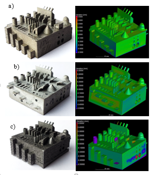
Figure 8 – SLM demonstrators as built and respective comparison with CAD file (right) at ±0,5mm. a) Ti6Al4V; b) Inconel 718; c) AlSi10Mg.

The analysis of the comparison for the SLM demonstrators pointed out that the material composition of the part affects the minimum feature possible, since the only appropriate demonstrator in order to reproduce all geometrical details was the one built up with Inconel 718, most probable because of the higher melting temperature of Inconel, allowing better metal melt pool control. The Ti6Al4V SLM demonstrator showed low deviation values even though it was not feasible to reproduce the columns with dimensions 0,1mm thin wall structures while also suffering from warpage and even detaching from the support structure (Figure 9).

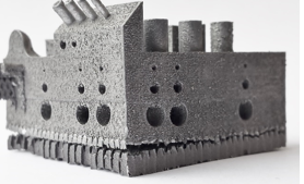
Figure 9 – Detail of the AlSi10Mg demonstrator.

Overall analysis on Figure 10 confirms the superior capability to reproduce fine details and better geometrical accuracy by SLM compared to EBM. However, the production of parts with tolerance inferior to ±0.5 mm appears to be the limit of SLM, being dependent on material choice for detailed feature reproduction.

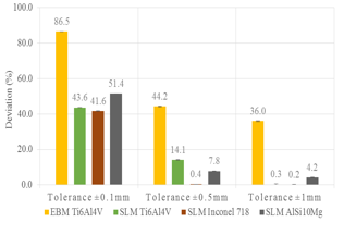
Figure 10 – Deviation comparison between the demonstrators made by different techniques.

The porosity analysis of the SLM Ti6Al4V demonstrator has been carried out revealing a residual porosity of 0.018% (Figure 11). The cause of this porosity was an obstruction of the 0.5 mm internal channels with residual powder.

Figure 11 – Porosity analysis of the SLM Ti6Al4V demonstrator.

Comparison of Computer Tomography against 3D scanning

The use of the 3D scanning generated insufficient results (Figure 12) since a firm attachment mechanism to the base was needed to prevent movement of the part during the capture of the features from more angles, which otherwise would diminish the precision. This led the structures to create shadows and the high reflectivity of the metal part hindered the surface recognition. This generated a partial representation of the demonstrator, rendering it unfit for total comparison with the original CAD file.

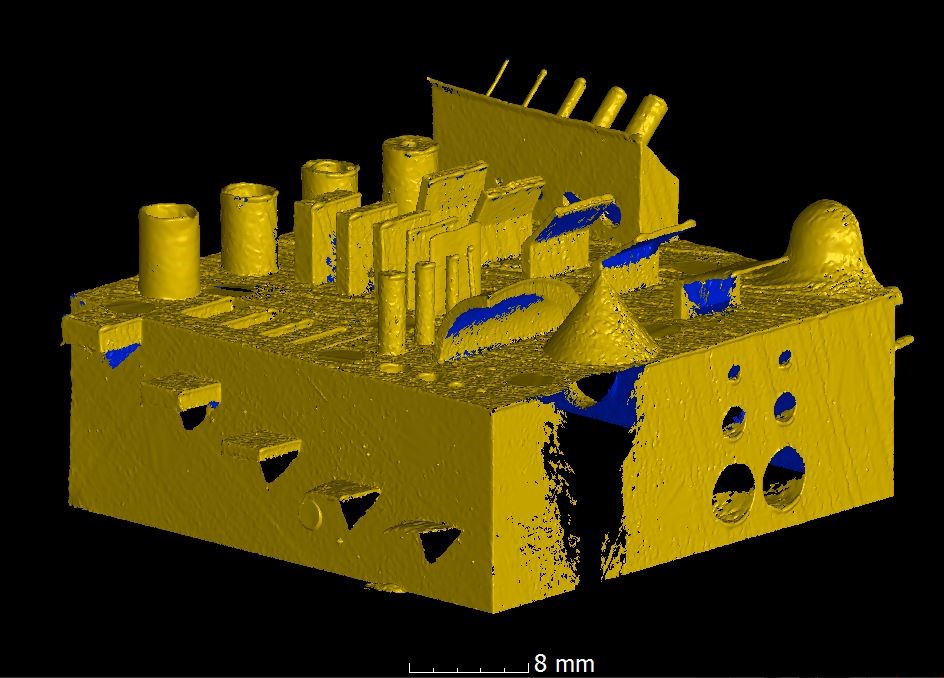
Figure 12 – Stl file obtained by the GOM Atos 45 with 0.4 mm dot size of the SLM Inconel 718 demonstrator.

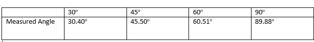
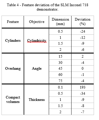
However, with the determined surface it was possible to make a analysis of the deviation of the features (Figure 13) using the software IMInspect 2015 IR4 by Innovmetric Software Inc. The results on Table 4 show higher deviations for lower dimension features, by which the machine was not capable of reproducing the 0.2 mm cylinder. These results corroborate the total comparison by computer tomography of minimum feature capability of features <0.5 mm.

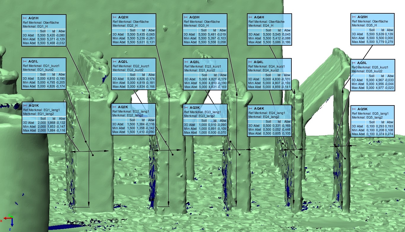
Figure 13 – Feature deviation measurement of the Stl. SLM Inconel 718 demonstrator obtained by the GOM Atos 45.

Table 4 – Feature deviation of the SLM Inconel 718 demonstrator.

On the other hand, the CT measurements were capable of fully characterizing the demonstrators, being able to display internal features, like the internal channels and the corresponding typical defects on overhang structures, that would be impossible to carry out by other methods.

Conclusions

Optical methods are insufficient for final part qualification due to their incapability to analyze internal features and the reflectivity of the surfaces of some parts that hinders accurate measurements. 3D scanning might be good for surface feature measurement, but it is insufficient for full characterization of an AM demonstrator of the addressed complexity aiming to explore the geometrical limits of additive manufacturing.

On the other hand, computer tomography can quantify all complex structures in scope of the proposed demonstrator and delivered deviation values of the measured structured, providing a good base for comparison across demonstrators made by different methods, materials and dimensions. Porosity or defects down to 3 µm can be determined by the used CT system.

The overall analysis confirmed the superior capability of SLM compared to EBM to reproduce fine details and better geometrical accuracy. However, the production of parts with tolerance inferior to ±0,5mm appears to be the limit of SLM, being dependent on material choice for detailed feature reproduction.

The subsequent comparison by means of computer tomography of the proposed demonstrators and the process conditions, allows one to deduce the most appropriate process parameters within a relatively small amount of experiments.

CT is the inspection and validation method of final parts that best fits the necessities of the AM industry. However, it is still a time-consuming procedure that requires several hours to set, run and analyze measurements and generate a report for each new part, which is not desired on an industrial environment.  With the expected expansion of the AM market, CT machines development requires more focus on the necessities of the AM industry in order to shorten scanning and analysis time and turn CT measurements into an online quality control method of final parts in the manufacturing process.

References

[1]W. E. Frazier, “Metal additive manufacturing: A review,” J. Mater. Eng. Perform., vol. 23, no. 6, pp. 1917–1928, 2014.

[2]I. Gibson, D. Rosen, and B. Stucker, Additive Manufacturing Technologies. New York, NY: Springer New York, 2015.

[3]S. L. N. Ford, “Additive Manufacturing Technology : Potential Implications for U . S . Manufacturing Competitiveness,” J. Int. Commer. Econ., vol. 6, no. September, pp. 1–35, 2014.

[4]I. Wing, R. Groham, and B. Sniderman, “3D opportunity for quality assurance and parts qualification: Additive Manufacturing clears the bar,” Deloitte Univ. Press, 2015.

[5]Y. Huang, M. C. Leu, J. Mazumder, and A. Donmez, “Additive Manufacturing: Current State, Future Potential, Gaps and Needs, and Recommendations,” J. Manuf. Sci. Eng., vol. 137, no. 1, p. 14001, 2015.

[6]L. De Chiffre, S. Carmignato, J. P. Kruth, R. Schmitt, and A. Weckenmann, “Industrial applications of computed tomography,” CIRP Ann. – Manuf. Technol., vol. 63, no. 2, pp. 655–677, 2014.

[7]F. Chen, “Overview of three-dimensional shape measurement using optical methods,” 2017.

[8]C. Xiaobo, X. Jun, J. Tao, and J. Ye, “Research and development of an accurate 3D shape measurement system based on fringe projection : Model analysis and performance evaluation,” vol. 32, pp. 215–221, 2008.

[9]P. Kühmstedt, C. Munckelt, M. Heinze, and C. Bräuer-burchardt, “3D shape measurement with phase correlation based fringe projection,” Opt. Meas. Syst. Ind. Insp., vol. 6616, pp. 1–9, 2007.

[10]P. Shah, R. Racasan, and P. Bills, “Comparison of Different Additive Manufacturing Methods Using Optimized Computed Tomography,” 6th Conf. Ind. Comput. Tomogr., vol. 1, pp. 1–10, 2016.

[11]S. Moylan, J. Slotwinski, A. Cooke, K. Jurrens, and M. A. Donmez, “An Additive Manufacturing Test Artifact,” vol. 119, pp. 429–459, 2014.

[12]A. Thompson, I. Maskery, and R. K. Leach, “X-ray computed tomography for additive manufacturing: a review,” Meas. Sci. Technol., vol. 27, no. 7, p. 72001, 2016.

[13]A. Kirchner, B. Kloden, J. Luft, T. Weisgarber, and B. Kieback, “Process Window for Electron Beam Melting of Ti-6Al-4V,” Euro PM2014 – AMTechnologies, pp. 6–11, 2014.

Highlights from LIA’s Lasers for Manufacturing Event (LME): Prima Power Holds Open House

By Ron Schaeffer

Prima Power was an exhibitor at Laser Institute of America’s LME 2018, held March 28-29 at the Renaissance Schaumburg Convention Center, Schaumburg, IL. After show hours on March 28, Prima Power hosted an Open House at its showroom in nearby Arlington Heights, IL. A large group of visitors, composed of laser industry experts, suppliers, and prospective customers were able to get a close-up view of the Prima Power Laser Next 3D Laser.

Thanks to a deep and unique experience of over 35 years in this field and to a continuous dialogue with customers and partners operating in the car industry, Prima Power has designed the new 3D laser machine for automotive production: Laser Next.  In developing Laser Next, Prima Power has focused on the achievement of the following main benefits for the user:

Maximizing throughput with a dramatic reduction of cycle times. During the last 10 years, the performance of Prima Power 3D laser machines for automotive applications has been growing steadily. With Laser Next, a fundamental step forward was made: productivity on a typical benchmark component (B-pillar) was raised by 25%. In other words, four Laser Next systems produce as much as five machines of the previous model.

Space-efficient layout both for stand-alone and multi-machine configuration. Space is money, and a well-conceived layout helps save square meters and optimizes plant logistics. The compactness of the installation further improves installing more machines, since you can have up to three units one next to the other connected to the same magnetic scrap conveyor, with no need of excavation works. Given the same area, in fact, it is possible to install more machines (e.g. four Laser Next instead of three units of the previous model). Considering the performance of Laser Next, the productivity per square meter ratio is simply astonishing.

Improved Overall Equipment Efficiency (OEE). For Laser Next, Prima Power capitalized on its experience of hundreds of installations for the 24/7 manufacturing of high-strength steel components, widely used in car production.

Every detail was studied and developed to maximize machine uptime. Maintenance was also lowered and simplified to reduce non-productive times and the need of specialized resources dedicated to these activities.

Laser Next has a working range of 3,050 x 1,530 x 612 mm and is equipped with 3 kW or 4 kW high brilliance fiber laser. Its compact focusing head, fully sealed for best protection, features direct drive motors, double protection SIPS, fully-metallic sensor, and Focal Position Control.


Dr. Kay Ball Releases Revision of Lasers – The Perioperative Challenge Through Laser Institute of America

ORLANDO, FL, March 21, 2018 — Published through the Laser Institute of America (LIA), renowned author Dr. Kay Ball has revised her book, Lasers – The Perioperative Challenge, to provide updated laser technology information to healthcare professionals. This is the fourth edition; the first was published in 1990, and Dr. Ball notes that much has evolved in the laser world since then.

“Dr. Ball’s book is an excellent read for medical personnel who are new to the use of lasers in medicine and wish to get a comprehensive understanding of lasers used in surgery and other areas outside of the OR. The book is written with the reader in mind and the information is easily understood,” said Gus Anibarro, LIA’s Education Director.

While writing this edition of her book, Dr. Ball focused on evidence from research and published articles on laser procedure applications and outcomes. Since she also travels the world to present laser technology, she included personal clinical experience and addressed common questions she receives from practitioners worldwide.

“Lasers: The Perioperative Challenge takes a complex technology and simplifies it for ready access by nurses, physicians, risk managers, and other healthcare providers. It offers valuable information on how to apply current standards and guidelines for a laser-safe environment,” said Dr. Ball. “I updated the book because there’s such a lack of comprehensive books on the market that address all aspects of laser technology in healthcare.”

The book highlights laser research and applications while incorporating current laser standards and guidelines. Sample laser safety policies provide templates for writing policies and procedures for the clinical environment.

“Everyone needs a really good reference or resource—especially if you’re just beginning your laser services,” said Vangie Dennis, who helped review the book and is the Executive Director of Perioperative Services for WellStar Atlanta Medical Center and Atlanta Medical Center South located in the metropolitan area of Atlanta. “It’s a really great product. It’s the ‘Alexander’ of the operating room—except for lasers.”

Within its 410 pages, the book contains more than 300 illustrations and graphics that are intended to deepen the reader’s understanding of foundational physics, safety, and administrative aspects. There is also an extensive glossary that offers an easy reference for laser terminology.

“As new procedures are introduced and accepted, laser safety is the strong foundation upon which practices are based. When safety is the primary cog in the wheel of laser applications, successful outcomes can be evidenced to validate practice changes.  Laser technology continues to advance and mature as safe practices are demonstrated while patients benefit,” said Dr. Ball in the preface of her book.

The 18 chapters are broken up into three sections: “Laser Biophysics, Systems, and Safety,” “Clinical Laser Applications,” and “Administrative Aspects of a Laser Program.”

The cost of the book is $80 for LIA members and $90 for non-members.

“This book is a ‘must’ for all professionals participating in laser surgery and therapy,” said Dr. Ball.

It can be purchased at www.lia.org/store/product/241.

About Laser Institute of America

Laser Institute of America (LIA) is the professional society for laser applications and safety serving the industrial, educational, medical, research and government communities throughout the world since 1968. http://www.lia.org, 13501 Ingenuity Drive, Ste 128, Orlando, FL 32826, +1.407.380.1553.

Design Guidelines For Laser Metal Deposition of Lightweight Structures

Design Guidelines for Laser Metal Deposition of Lightweight Structures

By Ake Ewald and Josef Schlattmann

Introduction

Weight critical applications, like parts in the aerospace industry, are driven by lightweight design. Titanium alloys have great potential in lightweight design of structural parts due to their excellent specific mechanical properties. Today, structural parts are manufactured in conventional milling processes. Titanium parts are characterized by poor milling behaviour as well as high material waste rates up to 95 % [1]. The Laser Metal Deposition (LMD) is a layer-wise manufacturing process for the production of three-dimensional complex parts [2].

LMD builds parts based on a nozzle-fed powder, which is solidified by a laser. The process can be used for surface cladding, repair and build-up of parts. For an effective industrial application, it is necessary to identify all advantages and disadvantages. A lowering of the introduction barrier can be achieved by design guidelines helping the engineer early in the product development. With LMD like Selective Laser Melting (SLM), existing manufacturing guidelines cannot be simply adopted. Due to the complex process constraints, a design guideline for LMD has been established.

Complex parts often share simple geometries as a basis. These shapes were identified and used to evaluate the applicability and effectiveness of LMD. Following established lightweight design guidelines, the presented guideline focuses on fine structures. In addition to the manufacturability, the building accuracy and the surface roughness have been investigated, since both have a significant influence on the product quality and the necessity of post processing towards the final shape of a part.

Investigation of process constraints

The investigations are performed with a Trumpf TruDisk 6001 multi-mode continuous wave disk laser with a laser power of 6 kW at a wavelength of 1.03 µm. A three nozzle processing head is used with a rotational table feeder (Fig. 1). The used Ti-6Al-4V powder is spherical and sieved to a fraction less than 80 µm.

Figure 1 Robot cell (TruLaserRobot).

Three different building strategies have been identified in a preliminary design guideline by Möller et al., 2016 [3]. Figure 2 shows the different building strategies. In S1 an inclination is achieved by a stepwise offset (a) between the layers (α = β = 0°). S2 rotates the platform to reach the inclination. The structure is manufactured vertically without an offset between the layers. S3 rotates the machine head to the inclination angle of the structure. The structure can be manufactured without an offset. Besides the three single building strategies, combinations of these are possible, which are not considered at this point. The preliminary guideline published by Möller et al. (2016) showed a high potential in the degree of freedom of building strategy S2 and S3 [3]. For this reason, these strategies were further investigated.

Figure 2 S1: horizontal offset between layer, S2: rotation of platform, S3: rotation of machine head

The mentioned fine structures have been classified as thin walls, curved walls, congregating and aggregating structures. The width of the manufactured structures has been set to a single layer width. The length has been set to 50 mm.

Thin Walls

The build-up of inclined thin walls has been made to investigate

  • the connection towards the platform,
  • the influence of the gravitation,
  • the building accuracy and
  • the influence on the wall surface.

Both strategies produce a constant and comparable wall thickness under (see Fig.3). It varies due to the surface roughness of about 150 µm. The variation of the measured angle is less than 1°.

Figure 3 Measured wall thickness of the inclined walls manufactured with S2 and S3.

The surface quality of a part has an influence on the appearance, the buy to fly ratio in case of a post processing, and the fatigue strength. The mean values of the surface roughness remain constant with rising inclination angles. The surface roughness of S3 is about 15 µm higher than with S2.


Curved Walls

Curved walls can vary in radius and angle. Curved walls can be divided into curves with their rotational axis parallel, and perpendicular to the building direction (z-axis, Fig. 4). The vertical built up of the curved walls with different radii can be seen in fig. 5.

Figure 4 Sketch of curved elements perpendicular (a) to the building direction and (b) parallel to the building direction.


Figure 5 Set of manufactured parallel curved elements with radius of 0 mm (left) to 30 mm (right).

The radii of the built walls are 0.15 mm to 0.4 mm smaller than expected. An intended vertical edge (radius of 0 mm) produces an outer radius of 3.58 mm. Without post processing, edges should be designed to allow a radius up to the layer width. The radius independent deviation allows the manufacturing in reproducible tolerance fields.

Congregating and Dividing Structures

The separation in congregating and dividing structures is based on the necessity of different manufacturing strategies and constraints in LMD (Fig. 6).

Figure 6 Sketch of the three defined congregating and dividing structures with building direction in z: (a) Y-branch, (b) overhang and (c) reversed Y-branch.

The manufacturing of regular and reversed Y-branches was realised by using S3. To achieve good results, binding on alternating branch sides is recommended (Fig. 7).


Figure 7 Sketch of the Y-branch (above), manufactured Y-branches with the angles β1 = β2 = 30° and β1 = β2 = 45° (below).


Additionally, overhangs were built on the manufactured vertical wall (Fig. 8) to evaluate

  • the connection between a thin rough wall and a manufactured wall,
  • the building accuracy, and
  • the boundary constraints.

The measured angles of the overhangs have an angle deviation of less than 1° up to a manufacturing angle square to the gravity (Tab. 1). This is comparable to the inclined walls. Overhangs show that overhangs with the same or smaller width can be manufactured on thin walls.

Figure 8 Manufactured overhangs with inclination angles from 30° to 90°.


Table 1 Measured inclination angles of the manufactured overhangs. The guidelines derived from the experimental investigation have been collected in a design catalogue according to the VDI 2222 in extracts shown in the figure 9.


Figure 9 Detail from the established design catalogue

Conclusion and Outlook

LMD offers a high degree of freedom in the design of parts. Lightweight parts can benefit from this flexibility. An industrial application can be achieved by design guidelines helping engineers to take the advantages and disadvantages of the LMD process into account during the design process.

The experimental investigation points out that structures based on the basic shapes are producible with constant geometric and surface tolerances, which allows reliable final machining. This is the basis for a successful design process. The building strategy S2 and S3 can be applied. The comparable results of S2 and S3 allow to choose the better fitting strategy for a specific use case.

By focusing on lightweight application, the following aspects have been achieved:

  • Investigation and manufacturing of basic shapes
  • Determination of process constraints
  • Draft of a design guideline.

The developed design catalogue builds a first step towards a comprehensive design guideline for LMD.


M.Sc. Ake Ewald has been a research assistant in the workgroup System Technologies and Engineering Design Methodology at the Hamburg University of Technology since 2013. He works in the methodical product development where he researches the methodical design of hybrid manufactured structural parts using LMD.

Josef Schlattmann is Univ.-Professor at the Hamburg University of Technology. He leads the workgroup System Technologies and Engineering Design Methodology.


References

[1] Allen, J. (2006) An Investigation into the Comparative Costs of Additive Manufacture vs. Machine from Solid for Aero Engine Parts, Rolls-Royce PLC Derby, UK.

[2] Ravi, G.A., Hao, X.J., Wain, N., Wu, X., Attallah, M.M. (2013) Direct laser fabrication of three dimensional components using SC420 stainless steel, Materials & Design, Vol. 47, 731-736.

[3] Möller, M., Baramsky, N., Ewald, A., Emmelmann, C., Schlattmann, J., (2016) Evolutionary-based Design and Control of Geometry Aims for AMD-manufacturing of Ti-6Al-4V Parts, Laser Assisted Net Shape Engineering 9 International Conference on Photonic Technologies Proceedings of the LANE 2016, S. 733–742, DOI: 10.1016/j.phpro.2016.08.075.

Register Now for the 2018 Lasers for Manufacturing Event!

By Ron D. Schaeffer, Ph.D.

The laser market is booming! While the U.S. economy in general is on a tear with the stock markets at record highs, the laser industry in particular is showing better financial numbers than the overall economy.  The total laser market was up approximately 20% in 2017 relative to 2016, making it one of the best years in the history of the laser industry, and it appears that 2018 could show just as much growth.

The laser market is growing due to manufacturers discovering the use of lasers to improve their processes. Don’t be left behind by your competitors. Attend the Lasers for Manufacturing Event® (LME®) to learn more about laser applications for manufacturing.

LME was conceived seven years ago as a venue to introduce commercial laser applications to a wider audience. LME 2018 will take place on March 28–29 at the Schaumburg Convention Center in Schaumburg, Illinois. Two other two-day conferences, Laser Additive Manufacturing (LAM®) 2018 and DigiFab Con 2018, will be co-located with LME. Registration to either conference will include admittance to LME.

LME is small enough that attendees can have personal contact with laser industry decision makers, yet big enough to attract a number of reputable exhibitors and industry icons. In addition to the exhibitor booths on the show floor, there will be technical talks and classes intended to promote the laser industry and to educate.

Why attend LME?

  • Interact with laser industry experts.
  • Find out if lasers can help with your manufacturing problems.
  • Network not only with the exhibitors but other attendees as well.
  • Sign up for the local field trip to Trumpf’s new Smart Manufacturing Facility. Opened in 2017, the facility features digitally connected production solutions for the sheet metal process chain.
  • Find a job in the photonics industry – even though this is a manufacturing event, it serves as a good venue for recent graduates because it is inexpensive and gives a lot of bang for the buck.
  • Increase the bottom line by increasing profits!


Program/Agenda

Keynote Speakers

One of the keynote addresses will be made by Dr. Geoff Shannon from Amada Miyachi discussing lasers for medical device manufacturing (Day Two from 2:15–2:45pm). Henrikki Pantsar from Trumpf Inc. will speak about lasers in heavy manufacturing (Day One at 2:00–2:30pm).

Tutorials

On Day One, I will be giving a tutorial on Current Trends in Laser Micromachining from 8:30 -10:00am.  This course will present information on precision laser subtractive manufacturing using mostly UV and USP (Ultra Short Pulse) lasers.  On Day Two, a tutorial will be given by David Havrilla from Trumpf on Laser Welding Techniques and Applications. Trumpf is an industry leader in the field of not only laser welding and material removal, but they also have a very large non-laser presence in the manufacturing industry.  This course dovetails perfectly with the proposed visit to the local Trumpf facility. These tutorials are free to attendees.

Lasers 101 and 102

These talks provide basic information on many aspects of laser technology. They start at about 10:15am each day and go until the end of the day. The topics will cover laser sources, beam delivery systems, laser safety, laser marking, laser cleaning, laser cutting, laser welding, laser cladding and optics.  These short presentations are given by many industry icons, and these presenters are generally available to not only answer questions but to meet informally afterward.

The best part about the 101/102 talks is that they are given on the floor of the exhibition, so there is no need to leave the exhibit floor to attend these talks.  In the past, most of these presentations have drawn a standing-room-only crowd.

Ask the Experts

Another extremely useful tool is the “Ask the Experts” booth, also located on the show floor. Spearheaded by industry veteran Neil Ball, this booth will be staffed by various laser experts and will be open for business throughout both days. The format is quite informal, and if the experts cannot answer your questions, they can usually direct you to someone in the hall who can.

Sponsors

It would be impossible to hold these conferences without the sponsorship of our corporate members.  The generous sponsors of LME are IPG Photonics, Laser Mechanisms and Trumpf, all recognizable names in the laser industry.

IPG manufactures laser sources and a standard array of laser machining systems and has held to the proposition of driving laser costs continually lower by revenue growth, volume growth and vertical integration.

Laser Mechanisms provides beam delivery components to customers all over the world and is recognized as an innovator in the field of beam delivery.

Trumpf manufactures laser sources, as well as components and industrial machining systems, and has been active in the industry for many years promoting the cutting edge applications.


Exhibitors

At the time of this writing, there are almost 50 exhibitors registered. These exhibitors range from companies providing laser sources (Amplitude, Ekspla, Light Conversion, Lumentum and SPI, for example) to companies that provide a complete industrial laser system (Alabama Lasers, GF Machining Solutions, Haas Laser Technologies and Lasea).  In addition, there are a number of optics and components companies to round out everything in between the laser source and the work piece. A number of companies involved in laser safety will be exhibiting, such as longtime LIA supporter Kentek. There will also be some exhibitors in the field of Laser Additive Manufacturing at LME, including companies like Trumpf, Alabama Laser, LPW Technology and Powder Alloy Corporation.

As with the sponsors, without the participation of these exhibitors, this exhibit would not be possible.  There is not enough space to recognize each of these exhibitors in this article, but each and every one is a valuable contributor to the overall success of the event.

What’s New in 2018?

Perhaps the most exciting new opportunity is the interaction of LAM and LME, which previously were completely separate conferences.

Digifab Con has also never before been held in conjunction with LME.  Produced by Fab Lab Hub, this program will explore how digital fabrication – like 3D printing, laser cutting and CAD – is changing the world.  Attendees will see exciting technologies like 3D printing, laser cutting, robotics and artificial intelligence and will have the opportunity to meet with visionaries, educators and innovators.  Learn how anyone can use digital fabrication to bring new ideas to life and change the world!

Registration is now open! For more information and to register, visit www.laserevent.org.

Ron D. Schaeffer is a technical consultant to PhotoMachining.


INCREASE YOUR ODDS OF SUCCESS AT LAM AND LME 2018

Here are a few tips that may help make your visit a success.

  • If possible, come with specific questions prepared in advance. If the project is still new, that is fine too, as general knowledge is still very useful especially in the first stage of many planned projects.
  • Take advantage of the Keynotes, courses, classes, talks, etc.
  • Take time to talk to ALL of the interesting vendors, even if you have come to the conference for a specific visit or meeting. There is a lot of information available – be a sponge!
  • Stay at the event hotel if possible as most of the laser vendors and sponsors will be staying there, and this is a perfect venue for less formal interactions – in other words you can grab someone in the hallways, restaurants or bar and get to know them. People do business with people!
  • Meet the LIA staff and LIA’s new Executive Director Nat Quick. These people are very smart and experienced and know a LOT of people, so they can connect you to the contacts you need. Plus, they are a bunch of good folks who you want to get to know regardless.
  • Join the Laser Institute of America as a member and receive all of the member benefits. Also, if you really want to get into the technical detail, consider attending our flagship conference, ICALEO, in the Fall.