Ultra-high-speed Laser Material Deposition for Internal Surfaces

By: Thomas Schopphoven, Fraunhofer Institute for Laser Technology ILT

Coatings for Wear and Corrosion Protection

When the integrity of a component is affected by the operational conditions, it may become necessary to additionally protect the material against this detrimental environment. Since most material damage processes, especially wear and corrosion, emanate from the surface or near surface regions, the application of coatings is the most suitable route to protect metallic surfaces. Coatings designed for the wear and corrosion protection must be an effective physical and chemical barrier, preventing the aggressive influence to the base material. The required thickness of the coating is dependent on the particular application and can range from a few up to several hundreds of micrometers. Generally, each coating system is aimed for specific functionalities, which among others include the chemical composition of the coating material, the adhesion to the base metal, the microstructure, the corrosion inhibition and the wear resistance.

While wear and corrosion protection coatings contribute to the performance, reliability and service life of many components across all industrial branches, these benefits often must be weighed against the environmental damage. For many years the most effective wear and corrosion protection systems were based on the use of chromate-rich surface treatments which turned out to potentially cause health problems for production workers and the community as a whole. The current legislation imposed by REACH (Registration, Evaluation, Authorization and Restriction of Chemicals) now prohibits the use of hexavalent chromium in almost all sectors. Similarly, this restriction applies to the use of nickel in electroplating, which has been classified as dangerous for the environment and toxic by the WHO (World Health Organization). As a result, REACH decisions have fostered the search for more advanced “green,” non-toxic and resource conscious coating technologies for the wear and corrosion protection. Many alternatives have been investigated, and so far the most promising technologies are thermal spray technologies, especially high velocity oxygen-fuel (HVOF) thermal spraying and laser material deposition (LMD).

The Search for “Green” Alternatives

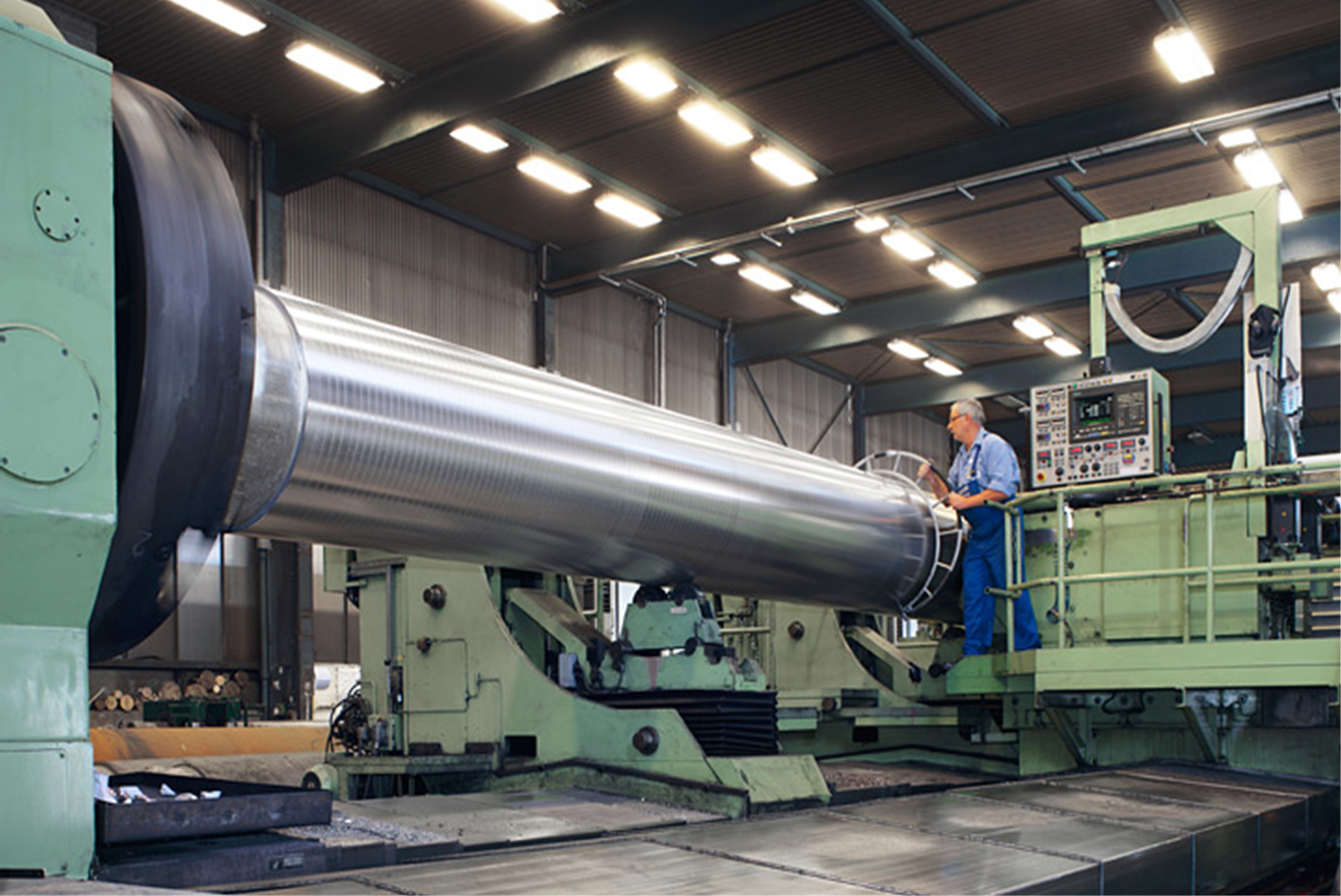
Fig. 1: Cylinder in the paper making industry
(Diameter: 1.000 mm, Length: 10 m)

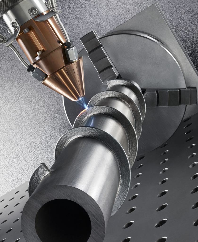
With HVOF thermal spraying, coatings out of a large range of materials can be applied, featuring a high wear resistance at relatively high deposition rates (1-4 kg/h). However, thermal spray coatings are technologically constrained in regards to the limited adhesion strength due to the poor mechanical bonding between coating and substrate. Moreover, thermal spray coatings are difficult to repair and often exhibit porosity levels in the range of 1-2%, lowering their corrosion resistance. Another disadvantage associated with HVOF thermal spraying is the comparatively high resource consumption of fuel, powder and oxygen. With LMD high-quality, almost 100% dense, pore- and crack-free coatings out of a wide variety of materials can be produced with a strong metallurgical bonding. Through a defined heat input and localized material deposition, LMD provides remarkable benefits over conventional welding processes and thermal spray technologies. Due to the very small heat input, a rapid solidification and a fine microstructure can be achieved with a property profile that meets, or even exceeds, the specifications of wrought or cast material. However, for the coating of large components, such as cylinders in the paper making industry (Figure 1), the LMD process is too slow (coating rate: 10-50cm2/min, deposition rate: < 0.5 kg/h). Furthermore, LMD layers are too large for many applications (>500 µm). In this layer thickness range, many conventional welding technologies, such as tungsten inert gas welding or plasma powder welding, offer cost advantages due to drastically lower investment costs. Various facilities and companies already addressed the reduction of processing times in LMD over the past years, by producing larger melt pools with higher laser powers in order to deposit more powder per time. In fact, the deposition rate could successfully be increased, but in turn the resource-consumption, as well as the heat input, was increased. The core issue—the simultaneous reduction of the layer thickness and coating time—could not be solved.

Ultra-high-speed LMD: The first economical coating process for thin, metallurgically bonded layers

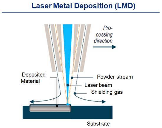
Fig. 2: Top: Schematic process principle for conventional LMD; Bottom: Schematic process principle for ultra-high-speed LMD

The maximum process speed as well as the minimum layer thickness in LMD is limited, because the heating and melting of the powder particles in the melt pool require a certain time and melt pool size. In Fig. 2 on the top, the process principle of LMD is schematically shown. Because the powder focus of conventional powder feeding nozzles is comparatively large (2-3 mm), most of the laser energy is transmitted to the substrate. As a result, most of the particles entering the melt pool have a considerably lower temperature Tp than the temperature of the liquid melt pool Tliq (Tp < Tliq). The general approach in ultra-high-speed LMD is to already heat the powder particles to melting temperature before they enter the melt pool (Tp ≈ Tliq), see Figure 2. To this, a larger amount of optical energy is deposited into the powder gas stream. At the same time, only a small fraction of transmitted energy is used to produce a thin melt pool on the surface of the substrate. Since both the necessary time and melt pool size are drastically reduced, a simultaneous increase of deposition speed by orders of magnitudes and the reduction of layer thicknesses to 10-250 µm can be achieved. Since less energy is deposited into the base material, only a very small heat affected zone (HAZ) and bonding zone with low dilution is formed. In order to deposit more energy into the powder gas stream, special powder nozzles are required, which produce a high optical density and a small powder focus diameter (0.5-1 mm).

Ultra-high-speed LMD for Internal Surfaces

Fig. 3: Schematic of inside processing head for ultra-high-speed LMD with integrated continuous coaxial powder nozzle

For ultra-high-speed LMD on outside diameters, standard optics and can be used for the processing of internal surfaces, i.e., for the coating of cylinder sleeves, bearings and housings of the oil and gas industry or plastic and extrusion components. However, special processing heads are required. The optical components, the powder feed, the water cooling system and the tubes for the shielding gas have to be integrated into a compact housing. For conventional LMD various processing heads for different inside diameters and immersion depths have been developed and are used in industry. Due to the limited available space, up to now only multiple-jet coaxial or lateral powder feeding nozzles are used for internal LMD processing heads. However, the required small powder focus diameters for ultra-high-speed LMD can currently only be achieved with coaxial powder feeding nozzles with a continuous powder gas stream. Based on the basic principles continuous coaxial powder feeding concepts for the ultra-high-speed LMD on outside diameters, Fraunhofer ILT developed a novel continuous coaxial powder feeding nozzle and adapted it for an inside LMD processing head from IXUN Lasertechnik, see Figure 3.

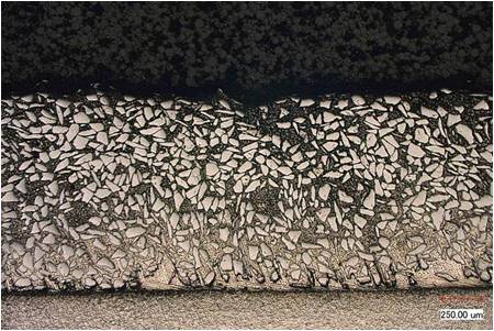
Fig. 4: Left: Inside processing head integrated into the ultra-high-speed LMD system; Right: Process image of ultra-high-speed LMD on an internal surface; Bottom: Cross-section of an ultra-high-speed LMD layer

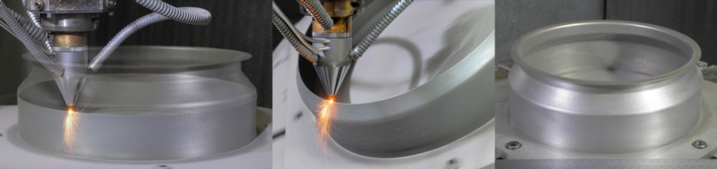
The inside processing head is integrated into a Hornet Laser Cladding high-speed LMD machine, see Figure 4, left. The system is based on a conventional lathe and retrofitted for ultra-high-speed LMD of rotationally symmetric components. With the system technology sound wear and corrosion protection layers in the thickness range of approximately 50-350 µm can successfully be deposited on the internal surface of cylindrical tubes with a minimal inside diameter of 100 mm with coating rates up to 200 cm2/min and deposition rates up to 1.5 kg/h, see Figure 4 on the right. On Figure 4 on the bottom a cross-section of a sound, metallurgically bonded ultra-high-speed LMD layer with minimal dilution and a thickness of approximately 100-150 µm is depicted.

Dipl.-Ing. Thomas Schopphoven is a Research Associate at Fraunhofer ILT and an expert for Ultra-high-speed Laser Material Deposition.

3D Printing of Net Shape Geometries by Laser Metal Deposition

By Carl Hauser 

Introduction
An additive manufacturing method developed by TWI within the framework of an EU-funded project could drastically reduce component manufacturing times.

TWI engineers have been using laser metal deposition (LMD) to produce net shape thin-walled engine casings, aiming to reduce the environmental impact of civil aerospace manufacturing.

In LMD, a weld track is formed using metal powder as a filler material which is fed, through a coaxial nozzle, to a melt pool created by a focused high-power laser beam. An inert gas carrier transports and focuses the powder into a small area in the vicinity of the laser beam focus (powder-gas beam focus). By traversing both the nozzle and laser, a new material layer develops with good precision and user-defined properties. The application of multi-layering techniques allows 3D structures to be created directly from a CAD model without the need of additional tooling. Historically, coatings and 3D objects deposited by LMD tend to be considered as near net shape.

The focus of the study was an axis-symmetric cylindrical casing with a maximum diameter of 300 mm, a wall thickness of 0.8 mm and a height of 88 mm (see Figure 1). The component is traditionally manufactured from a nickel alloy (Inconel 718), forming a complex geometrical topography requiring specialist tooling, all of which absorbs significant resource (six months lead time) and generates a large amount of waste material when manufactured.

Figure 1

From Design to Manufacture
Two years of development and six months of demonstration activity, led by the team at TWI’s Technology Centre in South Yorkshire, concluded the validation of CAM-style software tools created as a plug in to TWI’s ToolCLAD software: a software package being developed at TWI specifically for the LMD CAD-to-part-manufacturing process. The plug in maps a five-axis vector toolpath with deposition parameters to guide a three-axis coaxial LMD nozzle across a moving substrate manipulated by a two-axis CNC rotary table, creating a novel method of LMD manufacturing.

With precise synchronization of the movements of rotation and tilt of the substrate with incremental movements of the coaxial nozzle (predominantly in the +Z direction), a continuous spiraling weld track can be deposited or ‘grown,’ layer on layer, from out of the substrate. The helical multi-layering technique allows a thin-walled 3D contour to form, which accurately follows the changing directions of the original CAD surface profile (STL file). The process is analogous to a clay pot forming on a potter’s wheel. By allowing the substrate to control movement, rather than traversing the nozzle around a circular path, gives a consistent and regular weld track, and therefore, a good surface finish. Furthermore, the tipping of the substrate to axially align the orientation of the growing wall with the cladding nozzle allows overhanging features to be created without the need to build additional support structures.

A key innovation was the development and use of an adaptive slicing algorithm which automatically varies the numerical slice height (lead distance or pitch) between each helical revolution of the calculated tool path. The magnitude of the change is governed by the orientation of the facet (triangle) normal at the required slice height within the STL CAD model. However, during deposition, the actual build height is maintained at a fixed value to ensure a consistent surface quality. Hence, the adaptive slicing approach modulates the number of layers deposited per unit distance of build height which is governed by the tilt angle of the rotary table. Without this feature, printed parts would have a sizing error in the Z direction.

Modelling Heat Effects to Improve Precision
To assist with the experimental investigations the heat effects during LMD processing were replicated by Finite Element Analysis (FEA). With the utilization of FEA models, the prediction of the shape change of the LMD built casing could be calculated and compared to the target CAD geometry. The results from modelling agreed closely with visual observations, where much of the temperature dependent distortion occurred in the first 15-20 mm of build height. This caused the cylindrical wall to pull inwards. This distortion is linked to the build-up of cylindrical stress distributions during cooling coupled with the thermal shock of depositing the wall onto a substrate held at room temperature. The calculation of the magnitude of the distortion, layer on layer, helped to compensate the wall movement and maintain nozzle alignment on top of the growing wall through appropriate adjustment of the tool path.

Bringing Real-World Benefits
The high integrity of the final part, coupled with the low thermal loading imparted by the process, allowed it to be removed from the substrate with little further distortion. This is evident from the results of geometric 3D scanning. Overall tolerance across the largest diameter was ±250 µ. The wall thickness averaged 0.854 mm with a tolerance of 0.8 mm ±0.1 mm. The surface finish averaged 15-20 µ RA with the higher values centered on the fillet radii; probably because the powder-gas beam focus was not co-located directly on top of the growing wall during continuous reorientation of the table. This created a subtle stair step effect around a curved feature. It is important to note that a final heat treatment step would be necessary to alleviate residual stress that invariably builds up during LMD manufacture.

The LMD manufacture and subsequent dimensional measurement of a combustion casing prototype confirmed that the software and procedures developed in this study were capable of net shape manufacture. Furthermore, the LMD part was proven to have the same geometrical accuracy as a part produced by conventional manufacturing methods. The only difference was surface roughness, which increased from 0.8-1.6 µm to 15-20 µm in the LMD part; although this was still considered acceptable.

The key to the success of achieving the required geometric accuracy and surface finish was minimizing nozzle movement and allowing the substrate to do most of the work. The 7.5 hr build time was a significant reduction over the current six month lead time. However, the LMD productivity rate of 0.1 Kg/hr of deposited powder was considered very low. This can be ascribed to the requirement of wall thickness and surface finish which dictated weld track size and quality. The density of the final part was at least 99.5 percent. The weight of powder material fused in the final part was 750 g and 1.1 Kg of powder was pushed through the nozzle during manufacture, giving a 70 percent material efficiency. Conventional manufacturing routes for the casing (including the manufacture of tooling) generated several 10’s Kg of waste material.

The presented work is now being applied to other demonstrator applications across a range of different industrial sectors. This includes procedures to manufacture geometries with thicker walls, the addition of surface deposited features and parts with larger diameters.


Dr. Carl Hauser is a consultant on Additive Manufacturing and 3D Printing for TWI and would like to thank Neil Preece (TWI, UK) and Loucas Papadakis and Andreas Loizou (Frederick University, Cyprus) for assisting in the experimental work and process modelling.

Laser Metal Deposition & Laser Metal Fusion: Comparison of Processes & Their Uses

By Frank Geyer

Additive manufacturing, especially “3D printing”, is a hot topic for many industries. While 3D printing in plastics has already reached the consumer level, additive manufacturing processes using metals are more complex and require extensive material and process knowledge.

To understand 3D printing, it is important to first look at the three categories of manufacturing:

Subtractive manufacturing, or form alteration through material removal (i.e., machining), forming, or form alteration through heat or mechanical force (i.e., forging, bending), and generative or additive manufacturing which is the building of structures layer by layer (i.e., laser additive manufacturing, electron beam melting, laser metal deposition). In additive manufacturing, a three-dimensional object is created from a digital model. There are several metal based additive manufacturing methods available. This article will consider the two powder based laser additive processes: Laser Metal Deposition (LMD), also known as direct metal deposition, and Laser Metal Fusion (LMF), commonly known as powder-bed or 3D printing.

LMD utilizes a laser beam to generate a melt pool on the surface of the component (substrate). A stream of metal powder is blown into that melt pool and fused to the substrate. The result is a metallurgical bond between the coating and the substrate, providing a significantly improved bond compared to other coating or cladding methods.

LMD process diagram

For corrosion protection, materials like austenitic steels and nickel based alloys are deposited while for wear protection martensite steels, nickel and cobalt based alloys and carbide particles embedded in metallic matrices (i.e., tungsten carbides in nickel base matrix) are used. Other materials can be deposited as well, depending on the application.

An advantage of laser cladding over conventional methods is the precision of the layers, both in overlap and size, combined with the minimal dilution of the added material with the substrate.

The dilution zone is so small that, for many applications, a single layer is sufficient enough to have undiluted material at the surface.

Tungsten carbides embedded in nickel base matrix

Structure generation with LMD

LMD can be used for a variety of applications. Cladding applications include valve seats or coating along the edge of cutting blades, both of which require a high wear resistance. Turbine blade and shaft repairs, as well as commercial diesel engine parts (pistons, heads) and die repairs, are also highly feasible applications. LMD can also be used for generating structures from scratch or by building up an existing structure, for example to reinforce parts for specific load cases. As a very versatile process, LMD can add significant value to manufacturing and MRO based companies.

In contrast, Laser Metal Fusion (LMF) , or the process commonly known as metal 3D printing, is a powder-bed based laser fusion process that converts 3D digital data into a physical part, built up layer by layer. The part geometry 3D model is prepared in a special software that ‘slices’ the volume into very thin layers. Thicknesses between 20-100 µm are commonly used. A ‘scanning’ strategy is applied to each slice to optimize the fusion quality, part density and heat management throughout the build. Generating this file requires extensive material and process knowledge and is key to a successful build.

LMF (3D printing) process diagram

The LMF process starts with the application of a layer of metal powder to a substrate plate. The desired cross section of the geometry is then fused to the plate with a laser beam that is directed through a scanner optic. After the exposure the plate is lowered and the next layer of powder is applied. The process is repeated until the part is completed.

Build times depend on different factors, for example part size, layer thickness, materials, laser power, scanning speed and spot size and can range from several hours to weeks. While a print can be restarted if interrupted, the stopping point is always recognizable as the part temperature has changed. A dark line across the part shows when and where the interruption happened. Proper job preparation is crucial to avoid build errors mid-print, as you do not want to run out of powder half way through a three week job.

With the very high resolution of LMF it is possible to build fine and complicated 3D structures, to the extent that geometries that once required an assembly of several machined parts can now be redesigned and printed as a single part with the same or enhanced functionality.

Being able to produce internal and surface features within a single part also means that a completely different engineering approach is needed to fully utilize the advantages of this technology. Many restrictions and rules in designs that had to be manufactured by machining processes no longer apply. The 3D printed part design can have a complexity that is not possible to achieve otherwise. Engineers will have to learn how to design a part with such great freedom in complexity.

While 3D printing has become a buzzword that gets many people excited – and rightfully so –there is much more involved than just printing a part. When dealing with a metal in powder form, the grain size and structure are important and they play a significant role in the process as well as the final performance of the part. Currently there is a lack of powder manufacturing standards, specifically in regards to storing and handling, and a customer must be able to qualify powder prior to processing. In addition, the laser scanning strategy, laser power, spot size, choice of optics, cover gas and scanning path all affect the final structure. In the end, the resulting geometry is 100 percent welded, which in itself is a challenge for heat management and stress relief.

Once a build is completed the part needs to be removed from the machine. It then must undergo several post processing steps. The following actions do not necessarily have to be completed in this order, but all are required: post heat treatment (if higher densities are needed, this includes hipping), removal of support structures and the build plate, machining of any interface surfaces, and final surface treatments for example, bead blasting.

There are several industries already using 3D printing, including the dental , medical and prototype markets.

3D printed dental parts on build plate

Hip joint implants, crowns and bridges made of materials such as titanium, stainless steels and cobalt chrome, are examples of these applications.

One of the interesting aspects of these industries is that although the quantity of parts produced is high, there is no serial production. In other words each part is unique.

In aerospace, the ability to generate hollow and light ‘bionic’ structures allows for structural designs that have not been possible with conventional manufacturing methods. The use of 3D printing in metal has already moved from initial tryouts and prototypes to serial production. It is not “coming.” It is already “here.”

Additive manufacturing with lasers enables users to repair and make parts that have advantages over conventionally produced parts, and it can even eliminate the need for assemblies. The precision of LMD, which allows design engineers to add material characteristics exactly where needed, and the high resolution, “complexity-for-free” 3D printing are manufacturing methods that can and will open new metal based manufacturing capabilities that can replace or complement currently used processes.

Frank Geyer is the product manager for Additive Manufacturing & Laser Systems at TRUMPF Inc.

Digital Photonic Production – The Future of Laser Applications

By Reinhart Poprawe

One of the main challenges of modern manufacturing is the dilemma between scale and scope, i.e., the ability to produce high volumes at low prices, yet systematically integrating the increasing demand for individuality in the products. As a consequence, concepts for one piece flow at the cost of mass production are developed. Laser based manufacturing systematically resolves this dilemma and provides an extreme degree of flexibility and precision. In principle, parts can be designed totally independent of the manufacturing process, by focusing on the functionality of the part like static and dynamic stability or stiffness. In parallel, economic and ecologic demands such as light weight, deformation behavior by mesh structures and scaffolds or even other functionalities like conductivity can be integrated. Because the production chain leaps directly from the computer into the part and no tools are required, the process is also referred to as “Digital Photonic Production.” Examples of this process are Selective Laser Melting, Laser Metal Deposition and Ablation by ultrafast lasers.  Continue reading

LAM 2015 Delivers Revolutionary Applications in Additive Manufacturing

BY GEOFF GIORDANO

With more new workshops than ever purporting to give a true perspective on 3D printing and additive manufacturing, the Laser Institute of America’s Laser Additive Manufacturing (LAM®) Workshop has been ahead of the curve when it comes to realistic assessments of revolutionary industrial applications.

In its seventh year, LAM 2015 will again provide an intensive two-day immersion in the full spectrum of laser-based industrial additive applications — from traditional corrosion and wear protection and repair to the more hype-worthy powder-bed and powder-fed methods.

For the first time, LAM will not be held in the power-generation hub of Houston but in LIA’s hometown of Orlando, on Mar. 4-5 at the Embassy Suites Orlando – Lake Buena Vista South (Orlando, FL). LIA is a key part of the Florida High-Tech Corridor and the state’s photonics community, which includes the nearby College of Optics and Photonics at the University of Central Florida.

Continue reading