Design Guidelines For Laser Metal Deposition of Lightweight Structures

Design Guidelines for Laser Metal Deposition of Lightweight Structures

By Ake Ewald and Josef Schlattmann

Introduction

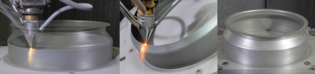
Weight critical applications, like parts in the aerospace industry, are driven by lightweight design. Titanium alloys have great potential in lightweight design of structural parts due to their excellent specific mechanical properties. Today, structural parts are manufactured in conventional milling processes. Titanium parts are characterized by poor milling behaviour as well as high material waste rates up to 95 % [1]. The Laser Metal Deposition (LMD) is a layer-wise manufacturing process for the production of three-dimensional complex parts [2].

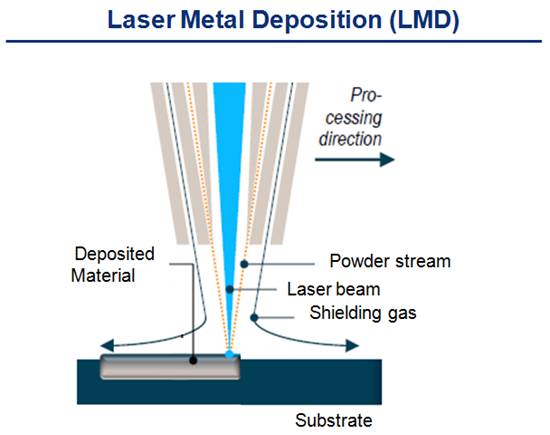
LMD builds parts based on a nozzle-fed powder, which is solidified by a laser. The process can be used for surface cladding, repair and build-up of parts. For an effective industrial application, it is necessary to identify all advantages and disadvantages. A lowering of the introduction barrier can be achieved by design guidelines helping the engineer early in the product development. With LMD like Selective Laser Melting (SLM), existing manufacturing guidelines cannot be simply adopted. Due to the complex process constraints, a design guideline for LMD has been established.

Complex parts often share simple geometries as a basis. These shapes were identified and used to evaluate the applicability and effectiveness of LMD. Following established lightweight design guidelines, the presented guideline focuses on fine structures. In addition to the manufacturability, the building accuracy and the surface roughness have been investigated, since both have a significant influence on the product quality and the necessity of post processing towards the final shape of a part.

Investigation of process constraints

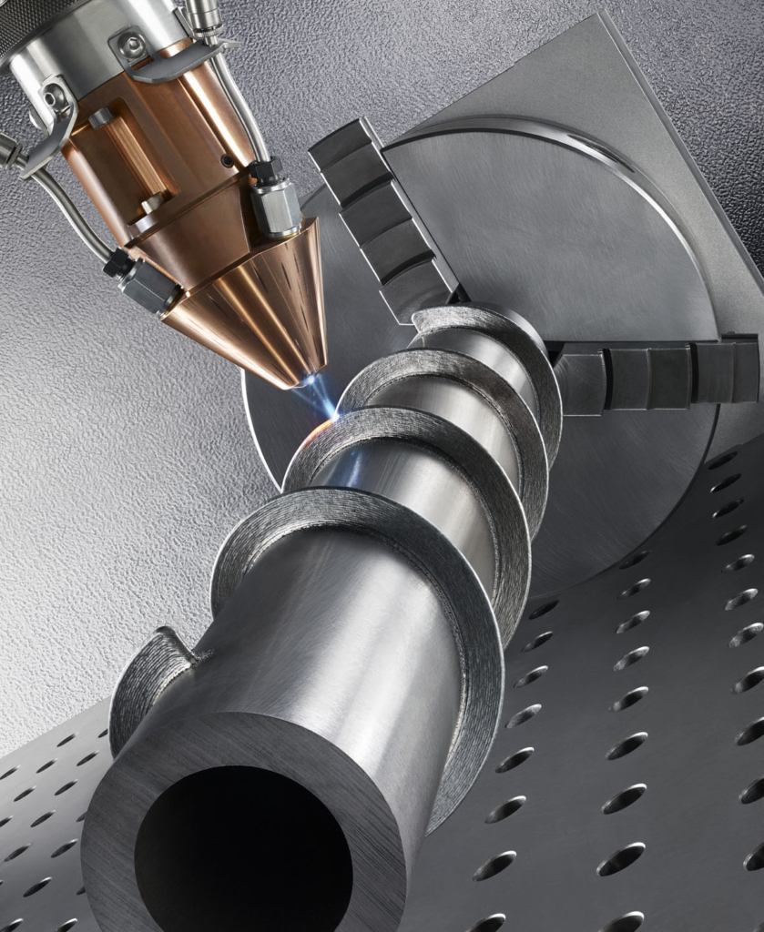
The investigations are performed with a Trumpf TruDisk 6001 multi-mode continuous wave disk laser with a laser power of 6 kW at a wavelength of 1.03 µm. A three nozzle processing head is used with a rotational table feeder (Fig. 1). The used Ti-6Al-4V powder is spherical and sieved to a fraction less than 80 µm.

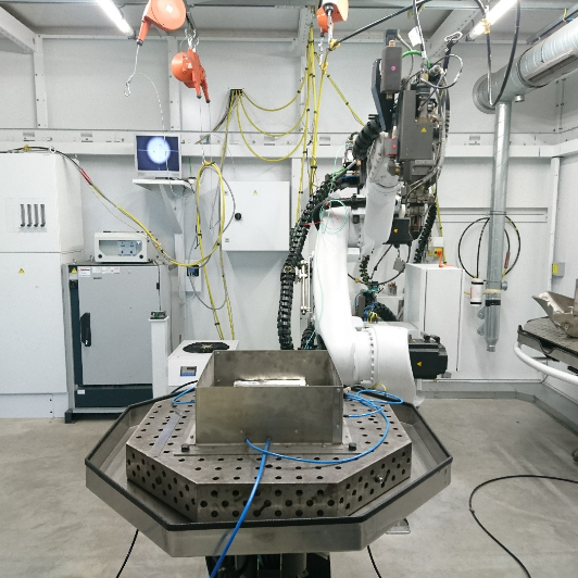
Figure 1 Robot cell (TruLaserRobot).

Three different building strategies have been identified in a preliminary design guideline by Möller et al., 2016 [3]. Figure 2 shows the different building strategies. In S1 an inclination is achieved by a stepwise offset (a) between the layers (α = β = 0°). S2 rotates the platform to reach the inclination. The structure is manufactured vertically without an offset between the layers. S3 rotates the machine head to the inclination angle of the structure. The structure can be manufactured without an offset. Besides the three single building strategies, combinations of these are possible, which are not considered at this point. The preliminary guideline published by Möller et al. (2016) showed a high potential in the degree of freedom of building strategy S2 and S3 [3]. For this reason, these strategies were further investigated.

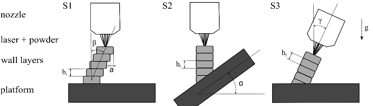
Figure 2 S1: horizontal offset between layer, S2: rotation of platform, S3: rotation of machine head

The mentioned fine structures have been classified as thin walls, curved walls, congregating and aggregating structures. The width of the manufactured structures has been set to a single layer width. The length has been set to 50 mm.

Thin Walls

The build-up of inclined thin walls has been made to investigate

  • the connection towards the platform,
  • the influence of the gravitation,
  • the building accuracy and
  • the influence on the wall surface.

Both strategies produce a constant and comparable wall thickness under (see Fig.3). It varies due to the surface roughness of about 150 µm. The variation of the measured angle is less than 1°.

Figure 3 Measured wall thickness of the inclined walls manufactured with S2 and S3.

The surface quality of a part has an influence on the appearance, the buy to fly ratio in case of a post processing, and the fatigue strength. The mean values of the surface roughness remain constant with rising inclination angles. The surface roughness of S3 is about 15 µm higher than with S2.


Curved Walls

Curved walls can vary in radius and angle. Curved walls can be divided into curves with their rotational axis parallel, and perpendicular to the building direction (z-axis, Fig. 4). The vertical built up of the curved walls with different radii can be seen in fig. 5.

Figure 4 Sketch of curved elements perpendicular (a) to the building direction and (b) parallel to the building direction.


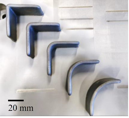
Figure 5 Set of manufactured parallel curved elements with radius of 0 mm (left) to 30 mm (right).

The radii of the built walls are 0.15 mm to 0.4 mm smaller than expected. An intended vertical edge (radius of 0 mm) produces an outer radius of 3.58 mm. Without post processing, edges should be designed to allow a radius up to the layer width. The radius independent deviation allows the manufacturing in reproducible tolerance fields.

Congregating and Dividing Structures

The separation in congregating and dividing structures is based on the necessity of different manufacturing strategies and constraints in LMD (Fig. 6).

Figure 6 Sketch of the three defined congregating and dividing structures with building direction in z: (a) Y-branch, (b) overhang and (c) reversed Y-branch.

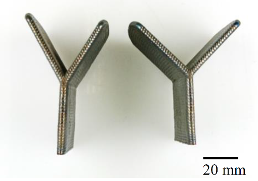
The manufacturing of regular and reversed Y-branches was realised by using S3. To achieve good results, binding on alternating branch sides is recommended (Fig. 7).


Figure 7 Sketch of the Y-branch (above), manufactured Y-branches with the angles β1 = β2 = 30° and β1 = β2 = 45° (below).


Additionally, overhangs were built on the manufactured vertical wall (Fig. 8) to evaluate

  • the connection between a thin rough wall and a manufactured wall,
  • the building accuracy, and
  • the boundary constraints.

The measured angles of the overhangs have an angle deviation of less than 1° up to a manufacturing angle square to the gravity (Tab. 1). This is comparable to the inclined walls. Overhangs show that overhangs with the same or smaller width can be manufactured on thin walls.

Figure 8 Manufactured overhangs with inclination angles from 30° to 90°.


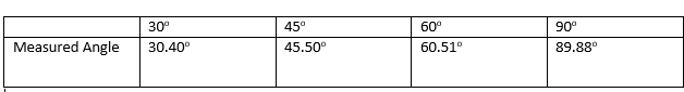
Table 1 Measured inclination angles of the manufactured overhangs. The guidelines derived from the experimental investigation have been collected in a design catalogue according to the VDI 2222 in extracts shown in the figure 9.


Figure 9 Detail from the established design catalogue

Conclusion and Outlook

LMD offers a high degree of freedom in the design of parts. Lightweight parts can benefit from this flexibility. An industrial application can be achieved by design guidelines helping engineers to take the advantages and disadvantages of the LMD process into account during the design process.

The experimental investigation points out that structures based on the basic shapes are producible with constant geometric and surface tolerances, which allows reliable final machining. This is the basis for a successful design process. The building strategy S2 and S3 can be applied. The comparable results of S2 and S3 allow to choose the better fitting strategy for a specific use case.

By focusing on lightweight application, the following aspects have been achieved:

  • Investigation and manufacturing of basic shapes
  • Determination of process constraints
  • Draft of a design guideline.

The developed design catalogue builds a first step towards a comprehensive design guideline for LMD.


M.Sc. Ake Ewald has been a research assistant in the workgroup System Technologies and Engineering Design Methodology at the Hamburg University of Technology since 2013. He works in the methodical product development where he researches the methodical design of hybrid manufactured structural parts using LMD.

Josef Schlattmann is Univ.-Professor at the Hamburg University of Technology. He leads the workgroup System Technologies and Engineering Design Methodology.


References

[1] Allen, J. (2006) An Investigation into the Comparative Costs of Additive Manufacture vs. Machine from Solid for Aero Engine Parts, Rolls-Royce PLC Derby, UK.

[2] Ravi, G.A., Hao, X.J., Wain, N., Wu, X., Attallah, M.M. (2013) Direct laser fabrication of three dimensional components using SC420 stainless steel, Materials & Design, Vol. 47, 731-736.

[3] Möller, M., Baramsky, N., Ewald, A., Emmelmann, C., Schlattmann, J., (2016) Evolutionary-based Design and Control of Geometry Aims for AMD-manufacturing of Ti-6Al-4V Parts, Laser Assisted Net Shape Engineering 9 International Conference on Photonic Technologies Proceedings of the LANE 2016, S. 733–742, DOI: 10.1016/j.phpro.2016.08.075.

Explore the Possibilities of Laser Additive Manufacturing at LIA’s 2018 LAM Conference

ORLANDO, FL (February 16, 2018) – The Laser Institute of America is pleased to announce that the 2018 Laser Additive Manufacturing (LAM®) conference will be held at the Schaumburg Convention Center in Schaumburg, IL, March 27–28. For the first time in its 10-year history, the conference will be co-located with the Lasers in Manufacturing Event® (LME®). LAM attendees will be granted free access to the LME exhibit, which takes place March 28–29.

The LAM conference is an excellent networking and educational opportunity for anyone interested in working in the additive manufacturing industry or discovering laser additive manufacturing solutions for their company.

Last year’s conference chairs will reprise their roles, with Milan Brandt of RMIT University continuing as the General Chair, and John Hunter of LPW Technology, Inc. and Minlin Zhong of Tsinghua University serving as Conference Co-chairs.

The first keynote speaker, a representative from America Makes, will address the benefits of public-private partnerships in the additive manufacturing industry. On the second day, keynote presenter Ehsan Toyserkani of the University of Waterloo will discuss recent developments in additive manufacturing in Canada.

The educational sessions following the keynote speeches will feature industry experts from companies including GE Additive, Flow Science, Caterpillar, the National Institute for Standards and Technology (NIST) and the Fraunhofer Institute for Laser Technology. The presentations will cover laser cladding and welding, laser metal deposition, powder bed fusion, directed energy deposition, process monitoring, quality assurance, sensor technologies, additive manufacturing standardization and strategies for growing the metal additive manufacturing industry.

At the end of the LAM sessions, attendees will be invited to attend a reception on the LME show floor and to explore all of the laser manufacturing technology solutions LME exhibitors have to offer.

LAM is made possible by sponsors Alabama Laser, TRUMPF, LPW and Laserline. Each company will have representatives available at both the LAM and LME events to answer any questions attendees may have.

For more information and to register, visit www.lia.org/lam.


About LIA

The Laser Institute of America (LIA) is the professional society for laser applications and safety serving the industrial, educational, medical, research and government communities throughout the world since 1968. www.lia.org, 13501 Ingenuity Drive, Suite 128, Orlando, FL 32826, +1.407.380.1553.

3D Printing of Net Shape Geometries by Laser Metal Deposition

By Carl Hauser 

Introduction
An additive manufacturing method developed by TWI within the framework of an EU-funded project could drastically reduce component manufacturing times.

TWI engineers have been using laser metal deposition (LMD) to produce net shape thin-walled engine casings, aiming to reduce the environmental impact of civil aerospace manufacturing.

In LMD, a weld track is formed using metal powder as a filler material which is fed, through a coaxial nozzle, to a melt pool created by a focused high-power laser beam. An inert gas carrier transports and focuses the powder into a small area in the vicinity of the laser beam focus (powder-gas beam focus). By traversing both the nozzle and laser, a new material layer develops with good precision and user-defined properties. The application of multi-layering techniques allows 3D structures to be created directly from a CAD model without the need of additional tooling. Historically, coatings and 3D objects deposited by LMD tend to be considered as near net shape.

The focus of the study was an axis-symmetric cylindrical casing with a maximum diameter of 300 mm, a wall thickness of 0.8 mm and a height of 88 mm (see Figure 1). The component is traditionally manufactured from a nickel alloy (Inconel 718), forming a complex geometrical topography requiring specialist tooling, all of which absorbs significant resource (six months lead time) and generates a large amount of waste material when manufactured.

Figure 1

From Design to Manufacture
Two years of development and six months of demonstration activity, led by the team at TWI’s Technology Centre in South Yorkshire, concluded the validation of CAM-style software tools created as a plug in to TWI’s ToolCLAD software: a software package being developed at TWI specifically for the LMD CAD-to-part-manufacturing process. The plug in maps a five-axis vector toolpath with deposition parameters to guide a three-axis coaxial LMD nozzle across a moving substrate manipulated by a two-axis CNC rotary table, creating a novel method of LMD manufacturing.

With precise synchronization of the movements of rotation and tilt of the substrate with incremental movements of the coaxial nozzle (predominantly in the +Z direction), a continuous spiraling weld track can be deposited or ‘grown,’ layer on layer, from out of the substrate. The helical multi-layering technique allows a thin-walled 3D contour to form, which accurately follows the changing directions of the original CAD surface profile (STL file). The process is analogous to a clay pot forming on a potter’s wheel. By allowing the substrate to control movement, rather than traversing the nozzle around a circular path, gives a consistent and regular weld track, and therefore, a good surface finish. Furthermore, the tipping of the substrate to axially align the orientation of the growing wall with the cladding nozzle allows overhanging features to be created without the need to build additional support structures.

A key innovation was the development and use of an adaptive slicing algorithm which automatically varies the numerical slice height (lead distance or pitch) between each helical revolution of the calculated tool path. The magnitude of the change is governed by the orientation of the facet (triangle) normal at the required slice height within the STL CAD model. However, during deposition, the actual build height is maintained at a fixed value to ensure a consistent surface quality. Hence, the adaptive slicing approach modulates the number of layers deposited per unit distance of build height which is governed by the tilt angle of the rotary table. Without this feature, printed parts would have a sizing error in the Z direction.

Modelling Heat Effects to Improve Precision
To assist with the experimental investigations the heat effects during LMD processing were replicated by Finite Element Analysis (FEA). With the utilization of FEA models, the prediction of the shape change of the LMD built casing could be calculated and compared to the target CAD geometry. The results from modelling agreed closely with visual observations, where much of the temperature dependent distortion occurred in the first 15-20 mm of build height. This caused the cylindrical wall to pull inwards. This distortion is linked to the build-up of cylindrical stress distributions during cooling coupled with the thermal shock of depositing the wall onto a substrate held at room temperature. The calculation of the magnitude of the distortion, layer on layer, helped to compensate the wall movement and maintain nozzle alignment on top of the growing wall through appropriate adjustment of the tool path.

Bringing Real-World Benefits
The high integrity of the final part, coupled with the low thermal loading imparted by the process, allowed it to be removed from the substrate with little further distortion. This is evident from the results of geometric 3D scanning. Overall tolerance across the largest diameter was ±250 µ. The wall thickness averaged 0.854 mm with a tolerance of 0.8 mm ±0.1 mm. The surface finish averaged 15-20 µ RA with the higher values centered on the fillet radii; probably because the powder-gas beam focus was not co-located directly on top of the growing wall during continuous reorientation of the table. This created a subtle stair step effect around a curved feature. It is important to note that a final heat treatment step would be necessary to alleviate residual stress that invariably builds up during LMD manufacture.

The LMD manufacture and subsequent dimensional measurement of a combustion casing prototype confirmed that the software and procedures developed in this study were capable of net shape manufacture. Furthermore, the LMD part was proven to have the same geometrical accuracy as a part produced by conventional manufacturing methods. The only difference was surface roughness, which increased from 0.8-1.6 µm to 15-20 µm in the LMD part; although this was still considered acceptable.

The key to the success of achieving the required geometric accuracy and surface finish was minimizing nozzle movement and allowing the substrate to do most of the work. The 7.5 hr build time was a significant reduction over the current six month lead time. However, the LMD productivity rate of 0.1 Kg/hr of deposited powder was considered very low. This can be ascribed to the requirement of wall thickness and surface finish which dictated weld track size and quality. The density of the final part was at least 99.5 percent. The weight of powder material fused in the final part was 750 g and 1.1 Kg of powder was pushed through the nozzle during manufacture, giving a 70 percent material efficiency. Conventional manufacturing routes for the casing (including the manufacture of tooling) generated several 10’s Kg of waste material.

The presented work is now being applied to other demonstrator applications across a range of different industrial sectors. This includes procedures to manufacture geometries with thicker walls, the addition of surface deposited features and parts with larger diameters.


Dr. Carl Hauser is a consultant on Additive Manufacturing and 3D Printing for TWI and would like to thank Neil Preece (TWI, UK) and Loucas Papadakis and Andreas Loizou (Frederick University, Cyprus) for assisting in the experimental work and process modelling.

Laser Metal Deposition & Laser Metal Fusion: Comparison of Processes & Their Uses

By Frank Geyer

Additive manufacturing, especially “3D printing”, is a hot topic for many industries. While 3D printing in plastics has already reached the consumer level, additive manufacturing processes using metals are more complex and require extensive material and process knowledge.

To understand 3D printing, it is important to first look at the three categories of manufacturing:

Subtractive manufacturing, or form alteration through material removal (i.e., machining), forming, or form alteration through heat or mechanical force (i.e., forging, bending), and generative or additive manufacturing which is the building of structures layer by layer (i.e., laser additive manufacturing, electron beam melting, laser metal deposition). In additive manufacturing, a three-dimensional object is created from a digital model. There are several metal based additive manufacturing methods available. This article will consider the two powder based laser additive processes: Laser Metal Deposition (LMD), also known as direct metal deposition, and Laser Metal Fusion (LMF), commonly known as powder-bed or 3D printing.

LMD utilizes a laser beam to generate a melt pool on the surface of the component (substrate). A stream of metal powder is blown into that melt pool and fused to the substrate. The result is a metallurgical bond between the coating and the substrate, providing a significantly improved bond compared to other coating or cladding methods.

LMD process diagram

For corrosion protection, materials like austenitic steels and nickel based alloys are deposited while for wear protection martensite steels, nickel and cobalt based alloys and carbide particles embedded in metallic matrices (i.e., tungsten carbides in nickel base matrix) are used. Other materials can be deposited as well, depending on the application.

An advantage of laser cladding over conventional methods is the precision of the layers, both in overlap and size, combined with the minimal dilution of the added material with the substrate.

The dilution zone is so small that, for many applications, a single layer is sufficient enough to have undiluted material at the surface.

Tungsten carbides embedded in nickel base matrix

Structure generation with LMD

LMD can be used for a variety of applications. Cladding applications include valve seats or coating along the edge of cutting blades, both of which require a high wear resistance. Turbine blade and shaft repairs, as well as commercial diesel engine parts (pistons, heads) and die repairs, are also highly feasible applications. LMD can also be used for generating structures from scratch or by building up an existing structure, for example to reinforce parts for specific load cases. As a very versatile process, LMD can add significant value to manufacturing and MRO based companies.

In contrast, Laser Metal Fusion (LMF) , or the process commonly known as metal 3D printing, is a powder-bed based laser fusion process that converts 3D digital data into a physical part, built up layer by layer. The part geometry 3D model is prepared in a special software that ‘slices’ the volume into very thin layers. Thicknesses between 20-100 µm are commonly used. A ‘scanning’ strategy is applied to each slice to optimize the fusion quality, part density and heat management throughout the build. Generating this file requires extensive material and process knowledge and is key to a successful build.

LMF (3D printing) process diagram

The LMF process starts with the application of a layer of metal powder to a substrate plate. The desired cross section of the geometry is then fused to the plate with a laser beam that is directed through a scanner optic. After the exposure the plate is lowered and the next layer of powder is applied. The process is repeated until the part is completed.

Build times depend on different factors, for example part size, layer thickness, materials, laser power, scanning speed and spot size and can range from several hours to weeks. While a print can be restarted if interrupted, the stopping point is always recognizable as the part temperature has changed. A dark line across the part shows when and where the interruption happened. Proper job preparation is crucial to avoid build errors mid-print, as you do not want to run out of powder half way through a three week job.

With the very high resolution of LMF it is possible to build fine and complicated 3D structures, to the extent that geometries that once required an assembly of several machined parts can now be redesigned and printed as a single part with the same or enhanced functionality.

Being able to produce internal and surface features within a single part also means that a completely different engineering approach is needed to fully utilize the advantages of this technology. Many restrictions and rules in designs that had to be manufactured by machining processes no longer apply. The 3D printed part design can have a complexity that is not possible to achieve otherwise. Engineers will have to learn how to design a part with such great freedom in complexity.

While 3D printing has become a buzzword that gets many people excited – and rightfully so –there is much more involved than just printing a part. When dealing with a metal in powder form, the grain size and structure are important and they play a significant role in the process as well as the final performance of the part. Currently there is a lack of powder manufacturing standards, specifically in regards to storing and handling, and a customer must be able to qualify powder prior to processing. In addition, the laser scanning strategy, laser power, spot size, choice of optics, cover gas and scanning path all affect the final structure. In the end, the resulting geometry is 100 percent welded, which in itself is a challenge for heat management and stress relief.

Once a build is completed the part needs to be removed from the machine. It then must undergo several post processing steps. The following actions do not necessarily have to be completed in this order, but all are required: post heat treatment (if higher densities are needed, this includes hipping), removal of support structures and the build plate, machining of any interface surfaces, and final surface treatments for example, bead blasting.

There are several industries already using 3D printing, including the dental , medical and prototype markets.

3D printed dental parts on build plate

Hip joint implants, crowns and bridges made of materials such as titanium, stainless steels and cobalt chrome, are examples of these applications.

One of the interesting aspects of these industries is that although the quantity of parts produced is high, there is no serial production. In other words each part is unique.

In aerospace, the ability to generate hollow and light ‘bionic’ structures allows for structural designs that have not been possible with conventional manufacturing methods. The use of 3D printing in metal has already moved from initial tryouts and prototypes to serial production. It is not “coming.” It is already “here.”

Additive manufacturing with lasers enables users to repair and make parts that have advantages over conventionally produced parts, and it can even eliminate the need for assemblies. The precision of LMD, which allows design engineers to add material characteristics exactly where needed, and the high resolution, “complexity-for-free” 3D printing are manufacturing methods that can and will open new metal based manufacturing capabilities that can replace or complement currently used processes.

Frank Geyer is the product manager for Additive Manufacturing & Laser Systems at TRUMPF Inc.

Additive Manufacturing with High-Performance Materials, Lightweight Structures by Laser Metal Deposition and Infiltration

By Frank Brueckner, Mirko Riede, Thomas Finaske, André Seidel, Steffen Nowotny, Christoph Leyens, Eckhard Beyer

Laser Metal Deposition (LMD) is used for repair/redesign as well as for manufacturing of new parts. Thereby, wire or powder filler material is reabsorbed in the laser-induced melt pool resulting in a strong metallurgical bond with the subjacent substrate in combination with a low dilution. Among various applications, LMD is an attractive process for jet engines to improve performance and efficiency as well as to contribute to more sustainability. In addition to design methods, such an improvement can be realized by lightweight structures and high-performance materials. Figure 1 shows the specific strength as a function of the temperature of high-performance materials. Since PMC structures are very important in the first stages of a jet engine, TiAl, Ni-base superalloys as well as CMCs are more relevant in hot engine areas.

Continue reading